QP-242E 工程师培训手册 (6.0).pdf.pdf - 第79页
FK-9F98-07 QP242E Training Text for Service Engineers 6th edition 8. MTU6 Adjustment [ 11 /16] Fuji Machine Mfg. Co., Ltd. Okazaki SMT Equipment Quality Assurance Dept. Technical Support Div. Section No.2 8- 11 O riginal…
FK-9F98-07 QP242E Training Text for Service Engineers
6th edition 8. MTU6 Adjustment [10/16]
Fuji Machine Mfg. Co., Ltd. Okazaki
SMT Equipment Quality Assurance Dept.
Technical Support Div. Section No.2
8-10
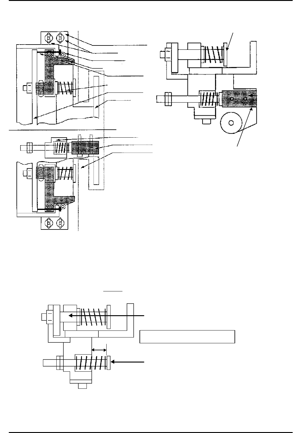
Top view
side view
Clamper shaft
Urethane
stopper
[8-20 ] Shuttle Jaw Adjustment
The following two figures show the shuttle at the retract limit as viewed from the top and the
side respectively. Use these figures as a reference.
1) Original_Position_TY measurement & shuttle tray holder clamper adjustment
a) Zero set the machine.
b) Remove the cam follower bracket. Move the stopper bolt to a position where the end of the
bolt will not hit the shuttle plate even if the shuttle moves to the retract limit. (If it is
screwed in as far as possible there will be no interference.)
c) With the shuttle at the advance limit or any position other than the retract limit (some
intermediate position is okay), change the set position to adjust the retract limit cushion
dimension A so that it is 13 mm as shown in the figure.
Lock bolts
Cam follower
Cam
Stopper bolt
Shaft clamper
Shuttle plate
Shuttle jaw
Retract limit cushion
Urethane stopper
Tray holder guide
Cam follower BKT
A:13mm
Shaft clamper
Retract limit cushion
Retract limit cushion adjustment
FK-9F98-07 QP242E Training Text for Service Engineers
6th edition 8. MTU6 Adjustment [11/16]
Fuji Machine Mfg. Co., Ltd. Okazaki
SMT Equipment Quality Assurance Dept.
Technical Support Div. Section No.2
8-11
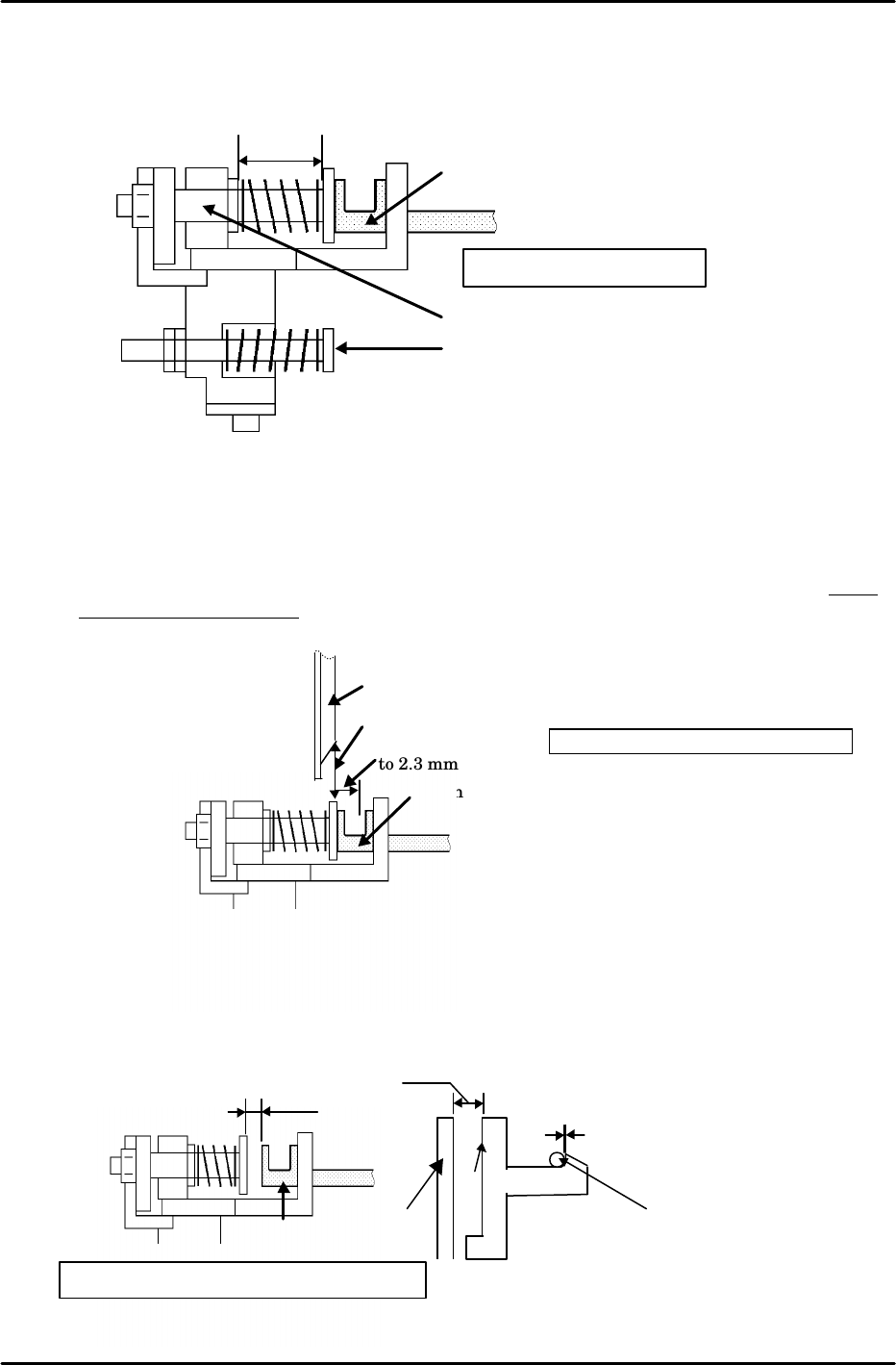
Original_Position_TY pre-adjustment
Flush
Tray holder
MTU tray holder stopper
Retract 2.2
to 2.3 mm
d) Likewise, with the shuttle at the advance limit or some position other than the retract
limit and the tray holder in the set status, adjust shaft clamper dimension B so that it is
18 mm as shown in the figure.
e) Move the shuttle to the advance limit using the following command operation;
[POSITION], [MTU], [SHUTTLE], [ADVANCE] and press START.
f) Set the tray holder and then retract the shuttle via inching.
g) As shown in the figure, from the position where the front of the MTU tray holder stopper
and the rear of the tray holder are on the same plane, retract the shuttle a further 2.2 to
2.3 mm (about 27 pulses) and record the servo count value of that position.
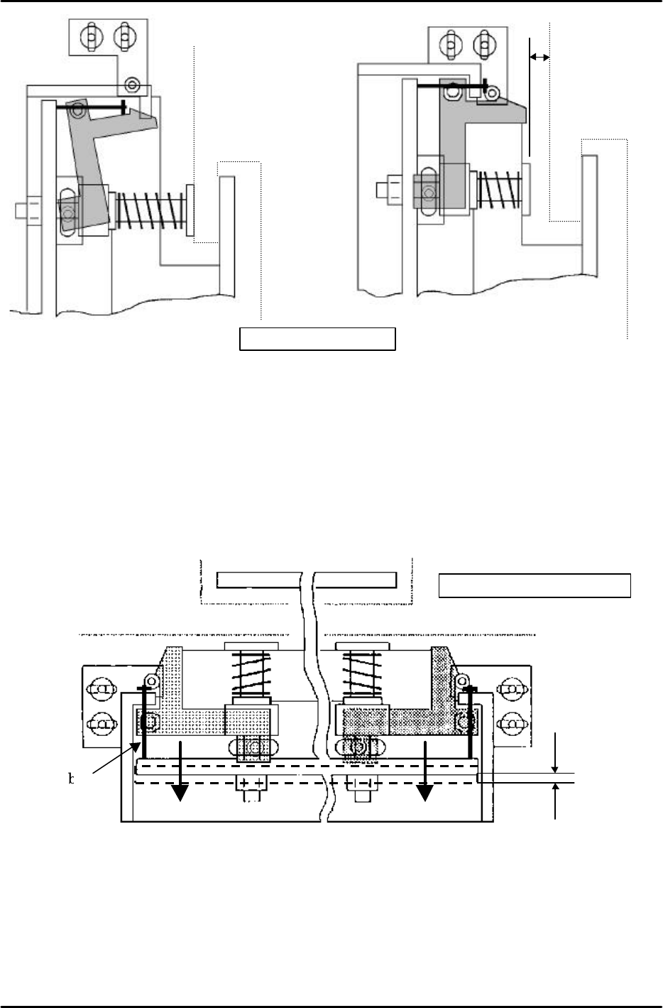
h) Install the cam follower bracket as shown in figure B. (Secure in place temporarily)
i) Adjust the cam follower position using the cam follower bracket such that side C of the
cam and the shuttle plate are approximately parallel and so that there is a gap of about 4
mm between the tray holder and the shaft clamper as shown in figure A.
B:18mm
Shaft clamper
Retract limit cushion
Tray holder
Shaft clamper adjustment
Tray holder
4mm
parallel
Cam
No clearance
Side C
Shuttle
plate
Top view
Cam
follower
Fig.
A Cam follower position adjustment
FK-9F98-07 QP242E Training Text for Service Engineers
6th edition 8. MTU6 Adjustment [12/16]
Fuji Machine Mfg. Co., Ltd. Okazaki
SMT Equipment Quality Assurance Dept.
Technical Support Div. Section No.2
8-12
0.5mm
Stopper bolt
Stopper bolt adjustment
j) From the position that satisfies these conditions retract the TY-axis another 1 mm (12
pulses). This position becomes Original_Position_TY.
k) In this position use the following command operation to automatically enter the Proper
data; [PROPER}, [ETC], [DEVICE], [ORG. POS], [TY], and [SET].
2) Stopper bolt adjustment
a) Attach the stopper bolt. (Secure in place temporarily.)
b) As shown in the figure below adjust the stopper bolt so that the shuttle plate is pushed in
on the advance limit side by 0.5 mm.
c) Move the shuttle to the advance limit and tighten the stopper bolt lock nut.
4mm
Fig.B Cam installation
After cam
installation
Prior to cam
installation
Top view
Top view