QP-242E 工程师培训手册 (6.0).pdf.pdf - 第52页
FK-9F98-07 QP242E Training Text fo r Service Engineers 6th edition 6. Proper Data Measurement [ 11 /20] Fuji Machine Mfg. Co., Ltd. Okazaki SMT Equipment Quality Assurance Dept. Technical Support Div. Section No.2 6- 11 …
FK-9F98-07 QP242E Training Text for Service Engineers
6th edition 6. Proper Data Measurement [10/20]
Fuji Machine Mfg. Co., Ltd. Okazaki
SMT Equipment Quality Assurance Dept.
Technical Support Div. Section No.2
6-10
[6-12] Line Scan Camera Test
Note: This test applies only to line scan cameras (camera types 4, 6, 7).
Because the measurement value can vary depending on the camera temperature,
the measurement should begin 5 minutes or more after the machine power has been
turned ON.
1) Place a black lens cover on the camera lens.
2) Execute an image acquisition operation as described in section [7-14], and verify (at [ZOOM
IN]) that there are no light and dark stripes (vertical or horizontal) at the individual pixels.
3) The evaluation standard is based on the average gray scale at adjacent pixels. (This average
value is obtained by taking the sum of the values displayed at the ZOOM IN screen and
dividing them by their number.) A value of +/- 6 or less is judged OK (normal).
Check the up/down average value at vertical stripes, and the right/left average value at
horizontal stripes. Average gray scale values within a 0-40 range are considered acceptable.
[Ex.1] <22 (A frame’s average value)> <25 (B frame’s average value)> <29(C)>
<26(D)> <21(E)> The result is judged OK (normal), because the difference
between adjacent average values is 6 or less.
[Ex.2] <22 (A frame’s average value)> <25 (B frame’s average value)> <32(C)>
<26(D)> <19(E)> The result is judged NG (bad camera adjustment), because the
difference between adjacent average values exceeds 6.
* When adjacent average values exceed +/- 6 at vertical stripes:
The line-scan camera’s internal “Odd Field” and “Even Field” balance probably needs
adjusting.
* When adjacent average values exceed +/- 6 at horizontal stripes:
This condition can be caused by an unstable image acquisition speed, or by a flickering
light source. Both possibilities should be investigated. The condition may also be caused
by cable noise. Replace the camera cable and check again.
* When the gray scale value is outside the 0~40 range:
This condition is probably caused by an unsuitable Cognex board. Check the Cognex
board, the jumper setting, and the cable connections, etc.
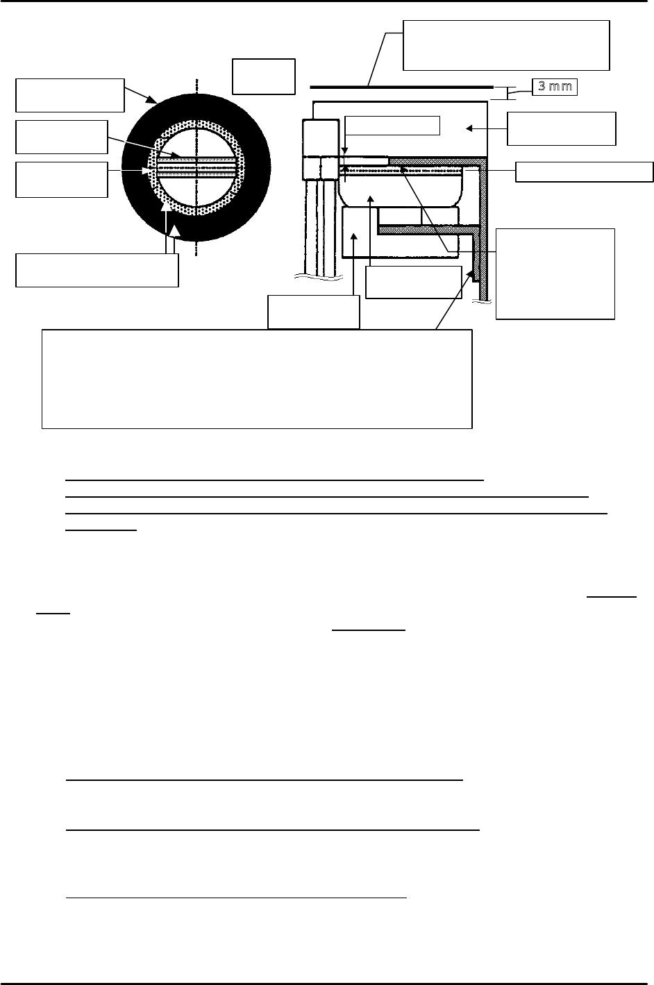
Straight fiber
light guide
Straight fiber
light guide
Double ring fiber
light guide
Double ring fiber
light guide
Fluorescent
ring light
Fluorescent
ring light
Align centers of double ring
fiber light and ring light
Image acquisition height
Nozzle end position when image is
acquired at a 0mm parts height.
3mm
Top face of glass board
Approx. 2.2mm
Adjust so that top
face of ring light is
slightly higher than
the bottom face of
bracket.
Camera
type7
In condition of index nozzle & front supply
& camera type 7, this
bracket is placed upside down. Also when the lighting condition is
other than above, it is lowered 15mm.
NOTE: In condition of index nozzle & front supply & camera type 7,
interference between lighting and head will occur if the height of
lighting and camera are the same other than above.
FK-9F98-07 QP242E Training Text for Service Engineers
6th edition 6. Proper Data Measurement [11/20]
Fuji Machine Mfg. Co., Ltd. Okazaki
SMT Equipment Quality Assurance Dept.
Technical Support Div. Section No.2
6-11
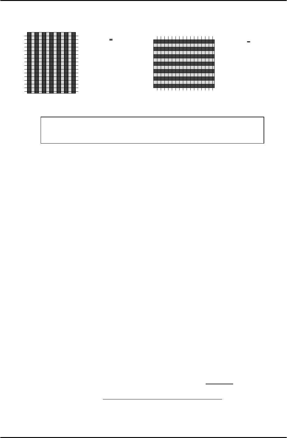
*** Vertical stripe display *** *** Horizontal stripe display ***
[6-13] Camera Center XC, YC Temporary Measurement
1) Mount a 10mm nozzle in the holder (for camera type 1, mount a 3.7mm nozzle). For CCD
cameras, use a back light nozzle. For line scan cameras, use a front light nozzle.
2) Execute the following command sequence to turn on the camera lamp and display the real
image: [CAMERA] à [CAMERA POS] à [PARTS CAMERA].
Because the real image cannot be displayed for single types, gauge by eye.
3) Perform an inching operation to move the head until the monitor center is aligned with the
nozzle center.
4) Execute the following command sequence to enter the Proper data: [RETURN] à
[ACQUIRED POS] à [XC/YC] à [SET].
[6-14] Focusing the Parts Camera
Note: Do not perform this adjustment until the [XC/YC] temporary measurement has been
completed.
1) Mount an appropriate nozzle in the holder. For camera types 1 and 6, mount a 7mm back light
nozzle. For camera types 2 and 3, mount a 15mm back light nozzle. For camera types 4 and
7, mount a 20mm back light nozzle (60mm fluorescent seal).
2) Turn on the “OUT Y002 NOZZLE VACUUM” I/O, then place a glass part jig (by hand) on the
nozzle.
Glass part jig:
For camera types 1, 6: 60-pin
For camera type 2: 108-pin
For camera type 3: 132-pin
For camera types 4 and 7: 284-pin
3) Execute the following command sequence: [SET] à [MANUAL] à [VISION] à [ADJUST] à
[ID CODE] à [CHECK IMG] à Enter module No. à [CR]. A [Mark Camera] [Parts Camera]
selection then displays in white. Use the [CAMERA SELECT] command to select the [Parts
Camera]. Use the [LIGHT SOURCE] command to select the light source type for the camera
which is being adjusted. For CCD cameras, select “back light”. For line scan cameras, select
“Front light 1”.
4) Execute the following command sequence to enter the glass part’s thickness: [GET ACQ] à
[VP SCAN HI]. Because the part’s thickness is different at camera 1 and at cameras 2 and 4,
enter the thickness as follows: cameras 1 and 6: 160, cameras 2 to 4: 230.
5) Execute a [RETURN] à[START] command sequence to raise the Z-axis by the amount of the
glass part thickness, then move the head to the [XC, YC] position measured above and
execute an image acquisition operation.
Note: The following two steps (6 and 7) apply to CCD cameras.
A B C D E F G H
* Normal gray
scale
|A-B|< 5
* Improper camera
adjustment
|A-B| > 5
B and C
C and D
•
•
Same manner
A
B
C
D
E
F
G
H
* Normal gray scale
|A-B|< 5
* Improper camera
adjustment
|A-B| > 5
B and C
C and D
•
•
Same manner
<<Judgement for CCD Camera Btightmess>>
Acquire the image of the glass parts with backlight. If the brightness of the nozzle
back plate is about 100, no problem. If the brightness is under 70, adjust again.
FK-9F98-07 QP242E Training Text for Service Engineers
6th edition 6. Proper Data Measurement [12/20]
Fuji Machine Mfg. Co., Ltd. Okazaki
SMT Equipment Quality Assurance Dept.
Technical Support Div. Section No.2
6-12
6) Execute the [RETURN] à [DIS REAL-IMG] commands to display the current real image at
the monitor.
7) While watching the monitor, turn the lens at the camera focusing side until the part’s legs are
clearly displayed.
8) Execute the [RETURN] à [ACQUIRED IMG] commands, then continuously press the [ZOOM
IN] command for as long as the brightness level remains acceptable. Next, execute the
[SCROLL] command and use the [Left], [Right], [Up], [Down] control keys to move the image
until the glass part’s legs are displayed. [STEP] can be pressed to change the number of pixels
traversed per operation. This function enables easy travel over long distances, and should be
used as necessary.
9) Although the value can vary somewhat depending on the camera being used, the focus is
acceptable if the difference between the gray value at the leg’s center and the gray value at
the body is 30 or less. If such a value is obtained, tighten the lens lock bolt (focusing is
completed).
10) If the obtained value is not 30 or less, repeat the adjustments described at items 4 to 9 above.
[6-15] Parts Camera X,Y,Q Measurement
1) Remove the nozzle and mount a resolution measurement jig.
* The jig to be mounted varies according to the camera type. Use of the wrong jig will result
in an error. Verify that the jig type is correct before beginning this measurement.
Camera type 1: Jig size: 8.4 x 8.4mm (BHPJ0460)
Camera type 2: Jig size: 27.4 x 27.4mm (BHPJ0190)
Camera type 3: Jig size: 36.8 x 36.8mm (BHPJ0220)
Camera type 4,7: Jig size: 73.6 x 73.6mm (BHPJ0170)
Camera type 6: Jig size: 18.4 x 18.4mm (BHPJ0180)
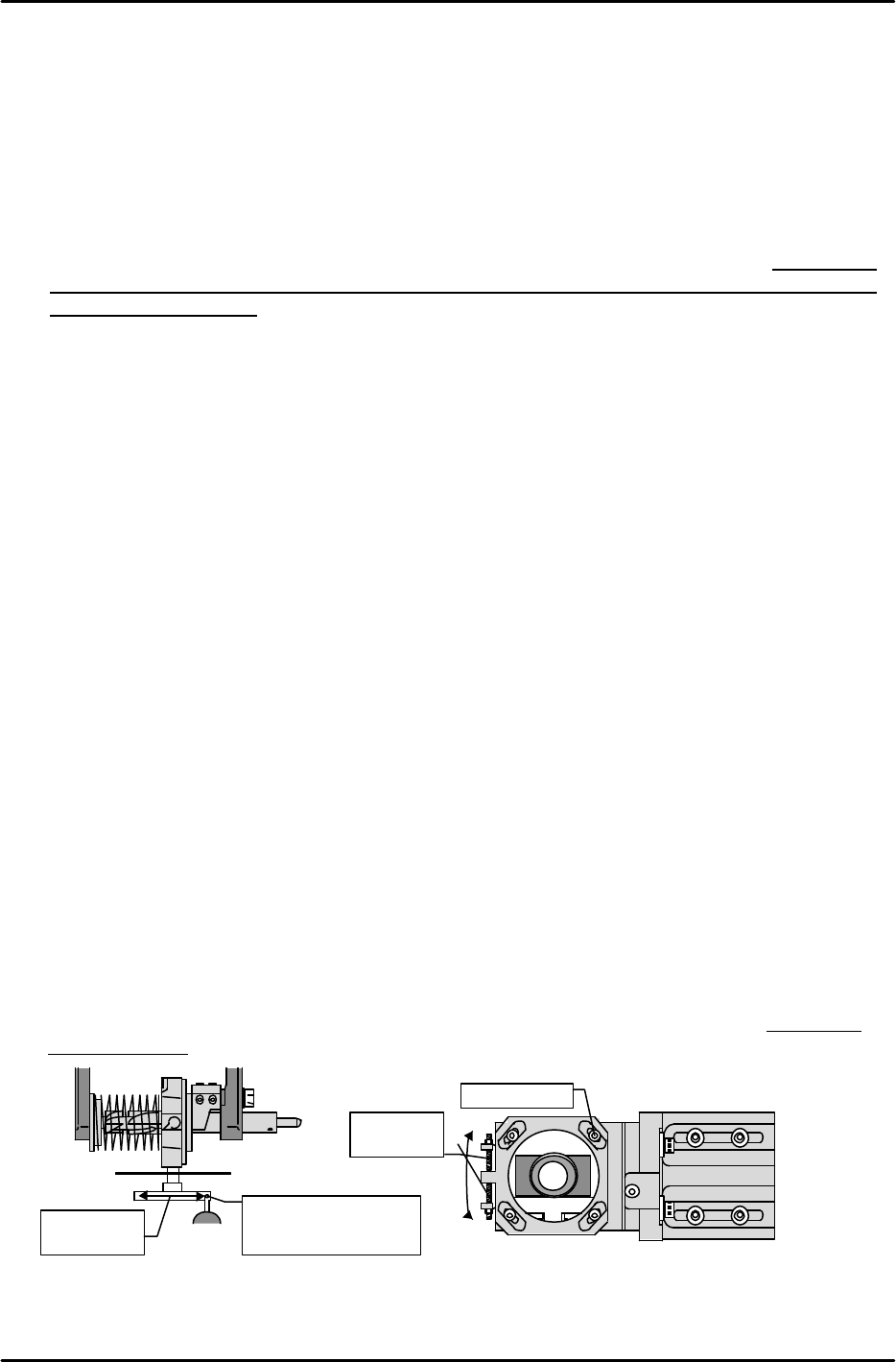
2) Place a dial gauge against one side of the jig, then turn the Q-axis until the jig is parallel (0.02
/ 100mm) to the X-axis.
3) Execute the following to raise the Z-axis, move the head to the [XC/YC] measured position
(see above), and perform the automatic measurement: [CAMERA]à [RESOLUTION] à
[PARTS CAMERA] à [START].
4) Following the automatic measurement, the “Parts Camera X,Y” values become the resolution
value. Note that the values varies according to the camera type as shown below.
Camera type 1 : 1435238(21.9um) < 1441792(22.0um) < 1448346(22.1um)
Camera type 2 : 4633395(70.7um) < 4653056(71.0um) < 4672717(71.3um)
Camera type 3 : 6271795(95.7um) < 6291456(96.0um) < 6311117(96.3um)
Camera type 4 & 7 : 2942566(44.9um) < 2949119(45.0um) < 2955673(45.1um)
Camera type 6 : 812647(12.4um) < 819200(12.5um) < 825753(12.6um)
5) If the X,Y measured values are outside the prescribed range, the camera height (focus) is
unsuitable. In this case, readjust the camera height until the X,Y values are within the
prescribed range.
[Ex] If the measured values are too low, lower the camera.
If both the X,Y values are within the prescribed range, proceed to the “Parts Camera Q”
adjustment.
6) Loosen the 4 lock bolts which secure the camera and turn the set screw until the Q-value is
within 0 +/- 655. After re-tightening the lock bolts, perform the measurement again.
Use dial gauge to
measure jig’s side
face
X-axis
direction
Q adj. set
screw
Lock bolt
カメラ
+
−