QP-242E 工程师培训手册 (6.0).pdf.pdf - 第74页
FK-9F98-07 QP242E Training Text for Service Engineers 6th edition 8. MTU6 Adjustment [ 6 /16] Fuji Machine Mfg. Co., Ltd. Okazaki SMT Equipment Quality Assurance Dept. Technical Support Div. Section No.2 8- 6 [8 -1 0 ] S…
FK-9F98-07 QP242E Training Text for Service Engineers
6th edition 8. MTU6 Adjustment [5/16]
Fuji Machine Mfg. Co., Ltd. Okazaki
SMT Equipment Quality Assurance Dept.
Technical Support Div. Section No.2
8-5
[8-9]
Zero Set Check
Remove the TZ-axis zero set sensor dog.
Once machine zero set has finished, MTU zero set begins. Trip the TY-axis negative side sensor (machine interior side)
prior to entering MTU zero set. If [START] is then pressed and zero set begins, the MTU will determine that the shuttle
is on the negative side thereby initiating TZ-axis zero set.
(If the TY negative side sensor is not tripped in time or if the positive side sensor is tripped, it is
determined that the shuttle is not in the retract position and the TY-axis moves first until it reaches the
negative side sensor before the TZ-axis moves. Once the TY-axis reaches the retract position, zero set of
the TZ-axis and TY-axis begins in that order.)
Use a scale to trip the TZ-axis zero set sensor and complete TZ-axis zero set. TY-axis zero set then
commences. Complete zero set of this axis in the same manner. Zero set is complete once both axes are
zero set. Maintain the 200 V power until adjustment is finished.
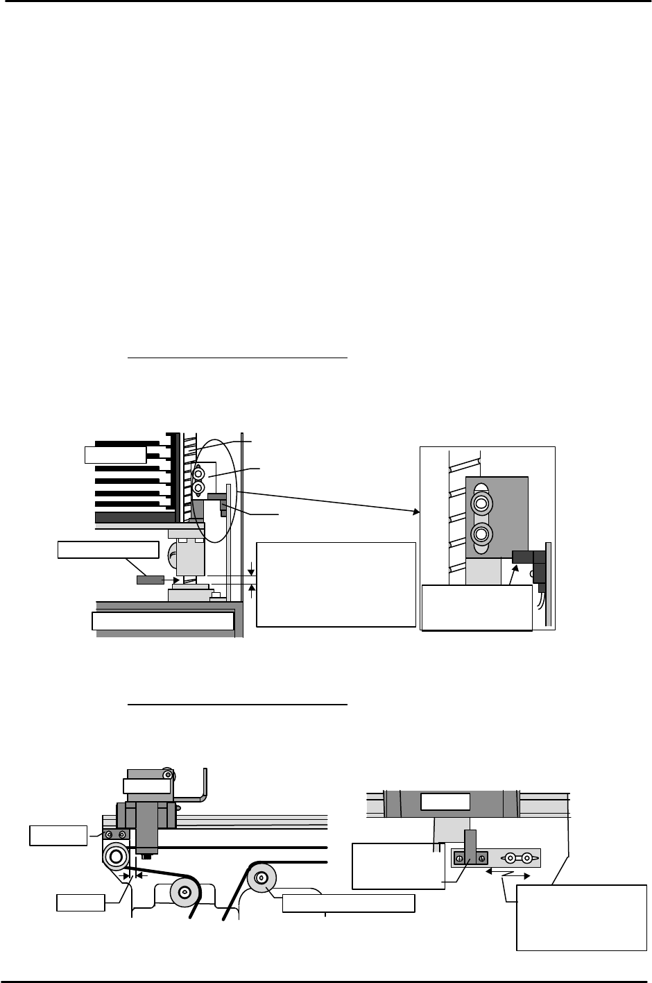
1) TZ-axis adjustment
Slowly raise the three TZ-axis ball screws and insert a 10 mm thick jig plate between
the stopper and each respective ball screw. Set the TZ-axis timing belt in this
position.
Note: There are three TZ-axis ball screws. Carefully attach the belt so that the height of
each of the ball screws is the same.
Belt tension: 46.90 Hz ± 10 Hz
Raise the axis 5 mm (+ 500 pulses, 15 mm from the mechanical stopper) from this
position and attach the dog that was removed previously. Adjust the dog up or
down so that the zero set sensor comes on.
2) TY-axis adjustment
Attach the timing belt with the shuttle in a position 3 mm (40 pulses) from the negative
side mechanical stopper.
Belt tension: 40.69 Hz ± 10 Hz
Move the sensor bracket to adjust the zero set sensor so that it comes on in a position
+ 65 pulses (105 pulses from the negative side mechanical stopper) from the position at
which the timing belt was installed.
Tray rack
TZ-axis ball screw
Dog
Sensor
Lower right front of MTU
10mm block jig
Adjust so that the
sensor comes on at
+ 500 pulses.
10mm
Insert the jig between the
ball screw and stopper of
each respective ball screw so
Shuttl
3mm
Stopper
Belt tension adj. pulley
Shuttle
Move the sensor
bracket to adjust the
sensor position so
that it comes on.
TY-axis position at + 65 pulses
Zero set
deceleration
sensor
FK-9F98-07 QP242E Training Text for Service Engineers
6th edition 8. MTU6 Adjustment [6/16]
Fuji Machine Mfg. Co., Ltd. Okazaki
SMT Equipment Quality Assurance Dept.
Technical Support Div. Section No.2
8-6
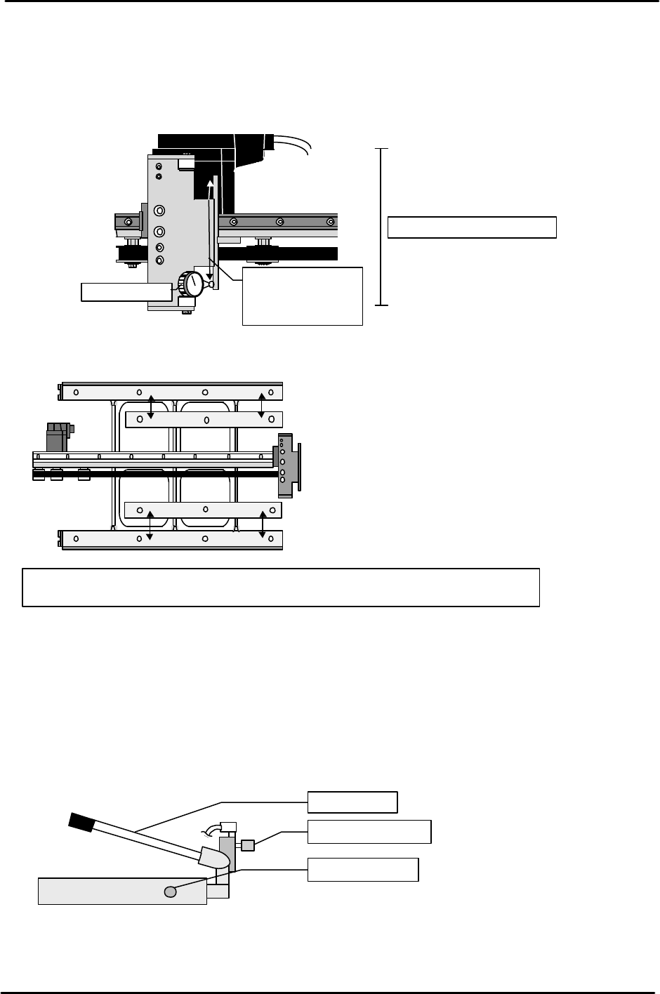
[8-10] Shuttle Parallel Measurement
From the operation display screen carry out the following command operation to
move the shuttle to the advance limit; [POSITION], [MTU], [SHUTTLE],
[ADVANCE], and then press START. In this position measure the parallelism of
both ends of the shuttle jaw. If the difference between the ends is greater than 0.2
mm, use the mounting screw clearance holes to adjust.
[8-11] Shuttle Slope Levelness Measurement
Attach a dial gauge to the machine placing head and measure the levelness of the
plastic surface attached to the top surface of the shuttle surface. Adjust by inserting
shims so that the variation from (1) to (4) is within 0.1mm and such that the variation
from (5) to (8) is within 0 to -0.1 mm of the respective slopes.
[8-12] MTU Descent Speed Adjustment
Raise the MTU to the maximum stroke using the hydraulic jack and use the speed
controller on the side of the jack to adjust the time from the opening of the hydraulic
jack valve to the end of descent, to between 6 and 10 seconds.
Tolerance : 0.2/100mm
0mm
( )
( )
100mm
TY
-axis
shuttle
Dial gauge
Move the shuttle
to the advance
limit and
measure.
Tolerances: Location (1) through (4) should be level within 0.1 mm.
Location (5) through (8) should be level within 0 to -0.1 mm of the applicable slopes.
1. 2.
3.
4.
5. 6.
7.
8.
1.(0mm )
2.( )
3.( )
4.( )
5.( )
6.( )
Speed controller
Descent valve
Ascent lever
FK-9F98-07 QP242E Training Text for Service Engineers
6th edition 8. MTU6 Adjustment [7/16]
Fuji Machine Mfg. Co., Ltd. Okazaki
SMT Equipment Quality Assurance Dept.
Technical Support Div. Section No.2
8-7
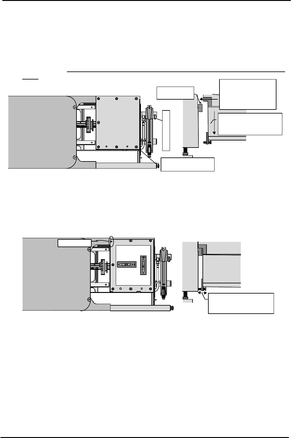
[8-13]
Connecting the MTU
1) Use the hydraulic jack on the MTU to lift the MTU to a height where the MTU clamping
brackets do not make contact with the machine locking pins.
2) Move the MTU to the position where the MTU clamping brackets align with the machine lock
pins. Be careful of the cables during movement.
3) Once the brackets are aligned with the pins, loosen the hydraulic jack valve and slowly lower the
MTU until it connects with the machine.
4) Verify that the contact surface of both brackets is actually making contact and then proceed to
the next item. (Use a clearance gauge to verify that there is a gap of less than 0.03
mm.)
[8-14]
Leveling
Remove the magazine rack, place a leveling device on the up/down plate, and check the level
in the front to back direction. (However, the leveling device is only used as a target. This is because
the up/down plate is not flat. Note also that it is not possible to adjust the level in the left to right
direction.) Use the angle adjustment bolt located on the bottom of the MTU to adjust the front to
back angle. After this is adjusted use the set screws on the top of the MTU to support the MTU so
that it is not tilted from front to back. After adjustment using the set screws, check the level again.
[8-15] Original_Position_TZ Provisional Measurement
Instead of the magazine set the jig that is the same height as the height from the bottom of the
magazine (magazine set surface, stationary side) to the highest level. While measuring the height
using a dial gauge, adjust the TZ-axis position via inching so that the jig is the same height as the
shuttle unit tray holder rail surface. Measure the rails on both ends of the shuttle unit and using
the lower side as a reference, set the provisional Original_Position_TZ at a position 0.5 mm (50
pulses) below the lowest side.
Top of the
Adjust the front to back
angle using the angle
adjustment bolt.
Set screw
MTU
Top of up/down
Y-direction
X-direction
Top of the
Move the lever up
and down to raise.
Loosen the air jack to
lower the MTU and
connect it to the machine.
Positioning
pin
Raise the MTU to a
height where there
is no contact with
the pins.
MTU