QP-242E 工程师培训手册 (6.0).pdf.pdf - 第11页
FK-9F98-07 QP242E Training Text for Service Engineers 6th edition 1. QP242E Initial Adjustment (1) [ 2 / 6 ] Fuji Machine Mfg. Co., Ltd. Okazaki SMT Equipment Quality Assurance Dept. Technical Support Div. Section No.2 1…
FK-9F98-07 QP242E Training Text for Service Engineers
6th edition 1. QP242E Initial Adjustment (1) [1/
6
]
Fuji Machine Mfg. Co., Ltd. Okazaki
SMT Equipment Quality Assurance Dept.
Technical Support Div. Section No.2
1-
1
[Chapter 1] QP242 Initial Adjustment (1)
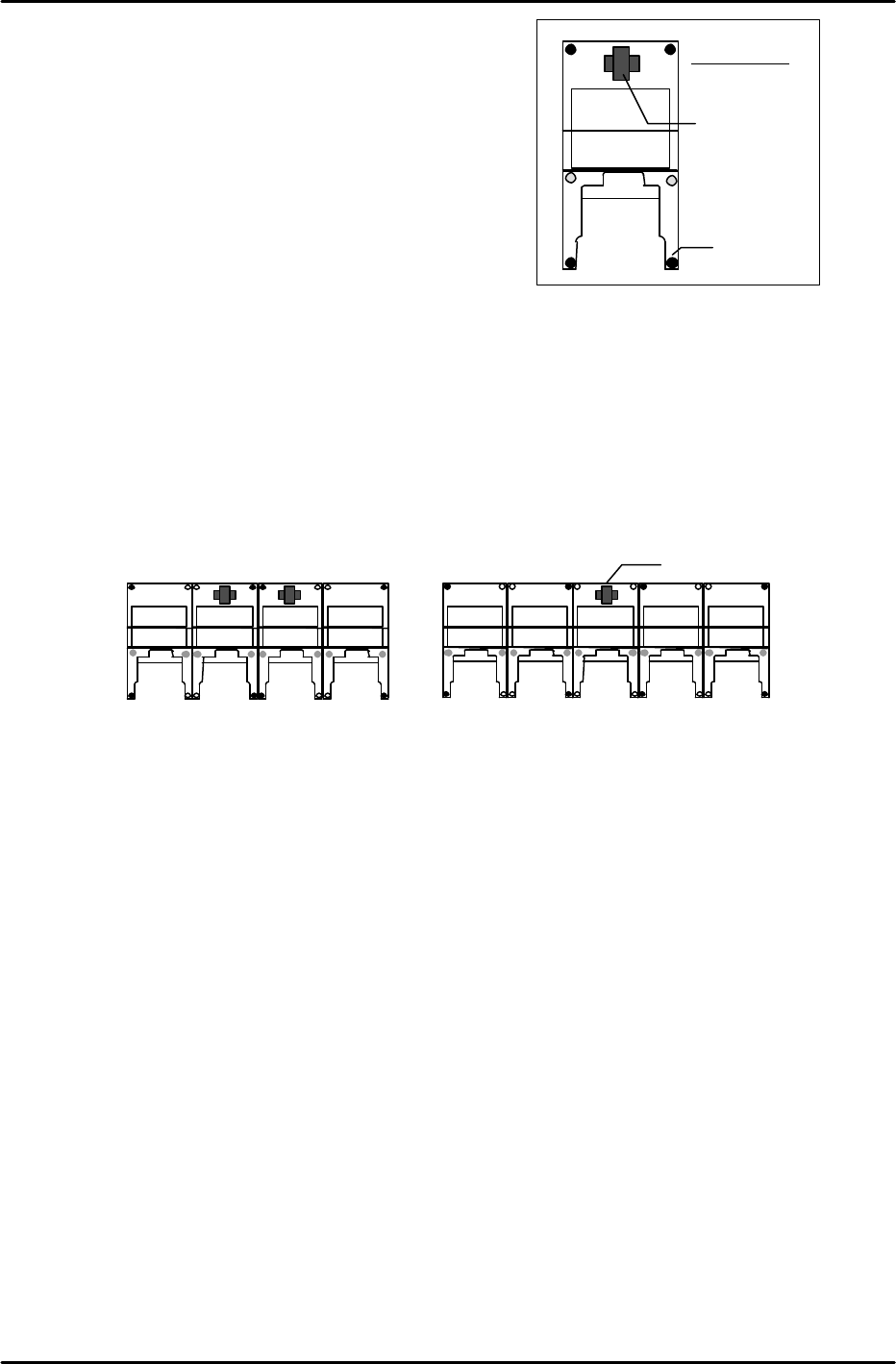
[1-1] Leveling the Machine
1) At systems with independent modules:
Place a level on the machine base and adjust the 6 leveling
bolts (black circles in figure at right) to level the
module in the front-back and right-left directions.
2) At systems with linked modules:
* When there are an even number of modules
(see figure below), place two levels on the two center
modules and turn the leveling bolts (shown as black circles in the figure below) to adjust the overall level.
After leveling the two center modules in this manner, verify that each of the modules is level. (The
further modules are from the center, the more likely they are to be out of level.
In such cases, further adjust the levels of the modules at both ends of the module row so that their levels
are the same, and are close to horizontal.)
* When there are an odd number of modules (see figure below), place a level on the center module and turn
the leveling bolts (shown as black circles in the figure below) to adjust the overall level. (The remaining
procedure is identical to that described above for an even number of modules.)
Leveling Device
(Level)
Leveling Bolt
Machine front
Leveling device (Level)
<Even number of modules>
Check
Check
<Odd number of modules>
Check
Check
Check
Check
FK-9F98-07 QP242E Training Text for Service Engineers
6th edition 1. QP242E Initial Adjustment (1) [2/
6
]
Fuji Machine Mfg. Co., Ltd. Okazaki
SMT Equipment Quality Assurance Dept.
Technical Support Div. Section No.2
1-
2
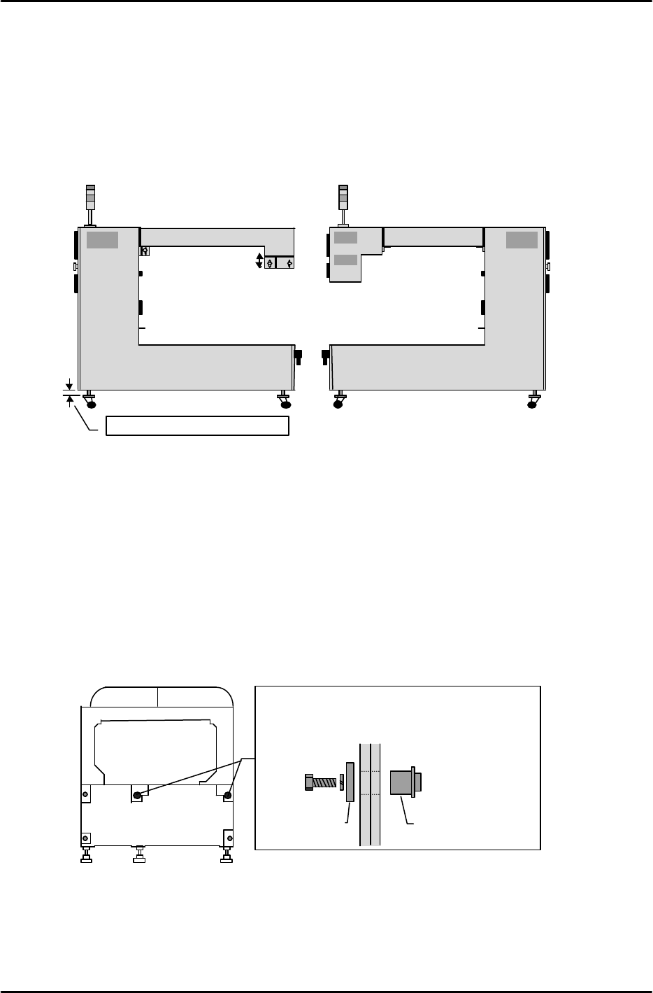
3) Leveling and connecting the ICM
1. After leveling the modules, install the ICM next to module 1.
2. Adjust the height of the ICM casters so that the top of the ICM operation monitor is the same height
as the top of the FRP cover at module 1. After adjusting all 4 casters to the same height, adjust the
square plates (one side of plates) on the casters so that they are parallel to the ICM's side face, then
secure in this position using the lock nuts.
3. After adjusting the ICM height, adjust the wiring duct box position and secure it. At rear
parts-supply machines, align the wiring duct box with the operation monitor at the front side.
[Procedure for linking modules]
*
The QP242 allows up to 6 modules to be connected to the ICM.
After leveling module 1 as described below, repeat this procedure for modules 2 to 6.
1) Level module 1. (Align board conveyance height)
2) Use a hand-lift to bring module 2 into position.
3) Align the module 2 height and front-back levelness with module 1.
4) Fne-adjust the height and front-back levelness until a nut can be inserted smoothly into the
positioning hole.
5) Level module 2. (After leveling, verify that the nut can be moved.)
6) Tighten the 5 bolts.
7) Check the levelness again.
8) Repeat the above procedure to connect the next module.
Adjust all 4 casters to the same height
View from ICM side face
Wiring duct box
Height adjustment
View from ICM side face
Wiring duct box
Rear parts-supply machineFront parts-supply machine
Machine front
Machine
rear
Machine
front
Machine rear
The two black circles indicate the positioning holes.
Adjust the height and front-back levelness so that the
nut canbe inserted smoothly.
NutWasher
FK-9F98-07 QP242E Training Text for Service Engineers
6th edition 1. QP242E Initial Adjustment (1) [3/
6
]
Fuji Machine Mfg. Co., Ltd. Okazaki
SMT Equipment Quality Assurance Dept.
Technical Support Div. Section No.2
1-
3
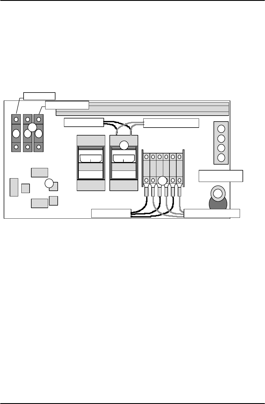
[1-2] Connecting the ICM and PLM
Perform the following procedure inside the top cover of the module at the Y-axis zero setting side:
1) Connect wires 901, 902, and 903. (As these are all power cables, be sure that they are secured
tightly.)
2) Connect CNP-10 and 12 as shown in the figure below. (Interlock wiring)
3) Connect wires 103 and 104. (As these are power cables, be sure that they are secured tightly.)
4) At odd-numbered modules, connect the cable from the ICM active hub to NET-1, and connect the
cable from NET-0 to the next module's NET-1. At even-numbered modules, connect the cable from the
previous module's NET-0 to NET-1, and leave NET-0 open.
5) Connect the air hose.
At inside ICM top cover:
1) Connect wires 901, 902, and 903.
(As these are power cables, be sure that they are secured tightly.)
2) Connect wires 103 and 104. (As these are power cables, be sure that they are secured tightly.)
3) Connect the interlock wiring to the MDL-I/F. (This cable is connected to GNP-12 at module 1.)
4) Connect each module's parts camera cable to the mutiplexer.
5) Connect each module's mark camera cable to the mutiplexer.
6) Connect each module's line scan camera cable and encoder cable to the CAM1-I/F and ENCODER1.
7) Connect the line scan camera's AV cable to CAM1-AV.
8) Connect the Arc net cable to the active hub.
9) Connect the air hose to the air coupler at the rear of the ICM.
901
901
902
902
903
903
ON
MITSUBI
SHI
C P 3 0 - B A
ON
MITSUBI
SHI
C P 3 0 - B A
CJ2
CJ1
CJ3
CJ4
NET 0
NET 1
104103
To next module From previous module
From previous module
To next module
CNP-10
CNP-12
To next module From previous module
Air hose port
1
2
3
5
4
C P 3 0 - B A