QP-242E 工程师培训手册 (6.0).pdf.pdf - 第19页
FK-9F98-07 QP242E Training Text for Service Engineers 6th edition 3. QP242E Initial Adjustment (2) [ 2 /12] Fuji Machine Mfg. Co., Ltd. Okazaki SMT Equipment Quality Assurance Dept. Technical Support Div. Section No.2 3-…
FK-9F98-07 QP242E Training Text for Service Engineers
6th edition 3. QP242E Initial Adjustment (2) [1/12]
Fuji Machine Mfg. Co., Ltd. Okazaki
SMT Equipment Quality Assurance Dept.
Technical Support Div. Section No.2
3-1
[Chapter 3] QP242E Initial Adjustments (2)
[3-1] Temporary Proper Data Transmission (Required Proper Data Details)
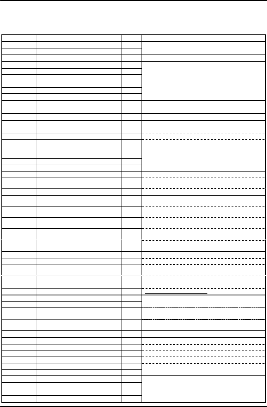
1) Using the following list as a reference, enter the temporary Proper data values at F4G.
Attr Caption Value Remarks
MQ2MT1 machine_type0 81
MQ2MT2 machine_type1 49
MQ2LG Language è 0: English 1: Japanese 2: French
MQ2REL Red Light 1024
MQ2YEL Yellow Light 36
MQ2BLL Blue Light 768
MQ2REB Red Flash 8
MQ2YEB Yellow Flash 8210
MQ2BLB Blue Flash 2241
User specified setting is used when designated.
MQ2MASA Machine Status A Note 4
MQ2MASB Machine Status B
Note 5
MQ2CMLP Command Line Port 12
MQ2DCSW Device Check SW 1
MQ2VFT Verifier Tool 0 Enter "2" when using the Handy Terminal.
MQ2BART Barcode Reader Type 0 Enter "5" when using the Handy Terminal.
MQ2DVCP Device Check Port 11
MQ2ESCP ESC Permission 1
MQ2MANP Man Permission 1
MQ2HTCC HT Comment Term. Code %
MQ2HTVC HT Verify Term. Code /
MQ2NPLM The Number of PLM è Enter the number of linked modules.
MQ2NVIPR The Number of Vision Processor è
Enter the number of ICM vision processing boards (COGNEX
boards).
MQ2MULT Multiplexe Type
Note 1
MQ2*MCMC PLM* Mark Camera MPX ch. No. Note 2
Specifies the multiplexer Ch. number where the mark camera is
connected.
MQ2*C(1or2)
MC
PLM* Parts Camera(1or2) MPX ch. No. Note 2
Specifies the multiplexer Ch. number where the parts camera (1
or 2) is connected.
MQ2*C(1or2)
LC
PLM* Parts Camera(1or2) LSO ch. No. Note 2
Specifies the LSO board Ch. number where the parts camera (1 or
2) is connected.
MQ2*C(1or2)
LB
PLM* Parts Camera(1or2) LSO board
No.
Note 2
Specifies the LSO board number where the parts camera (1 or 2) is
connected.
MQ2*C(1or2)
VB
PLM* Parts Camera(1or2) VP board No. Note 2
Specifies the vision processing board Ch. number where the parts
camera (1 or 2) is connected.
MQ2*HDT PLM* Head Type è Single holder type: 0 Index holder type: 1
MQ2*DVT PLM* Device Type è MFU5:0 MFU58:1 MTU6:2 MTU71:3
MQ2*C(1or2)
AT
PLM* Parts Camera(1or2) Type
è
1 2 3 4 6 7
MQ2*MASA PLM* Machine Status
Note 3
MQ2*PECW
PLM* Parts Eject Conv Width è MTU6 used M=74 MTU71 used M=50 MTU not used M=27
MQ2*MDLW
PLM* Module Width è
0:600mm 1:760mm 2:800mm
(V1.80 or newer)
Note 7
MQ2*MCGN PLM* Mark Camera Gain 0
MQ2*MCOF PLM* Mark Camera Offset 0
MQ2*C(1or2)
GN
PLM* Parts Camera(1or2) Gain Note 6 Camera type 1=0, 2=0, 3=0, 4=168, 6=0, 7=128
MQ2*C(1or2)
OF
PLM* Parts Camera(1or2) Offset Note 6 Camera type 1=0, 2=0, 3=0, 4=128, 6=0, 7=128
MQ2*OPIN Counter Output Interval 200
MQ2*EPX PLM* Escape Position X è Front:-105000 Back:105000
MQ2*EPY PLM* Escape Position Y è Front:-170000 Back:170000
MQ2*EPZ PLM* Escape Position Z
Note 7
MQ2*EP2X PLM* Escape Position2 X è Front:-90000 Back:90000
MQ2*EP2Y PLM* Escape Position2 Y 0
MQ2*EP2Z PLM* Escape Position2 Z 0
MQ2*PUT1 PLM* Pickup Timer 100
MQ2*PUT2 PLM* Pickup Timer_2 200
MQ2*PUT3 PLM* Pickup Timer_3 50
MQ2*PMTM
PLM* Placement Timer 50
FK-9F98-07 QP242E Training Text for Service Engineers
6th edition 3. QP242E Initial Adjustment (2) [2/12]
Fuji Machine Mfg. Co., Ltd. Okazaki
SMT Equipment Quality Assurance Dept.
Technical Support Div. Section No.2
3-2
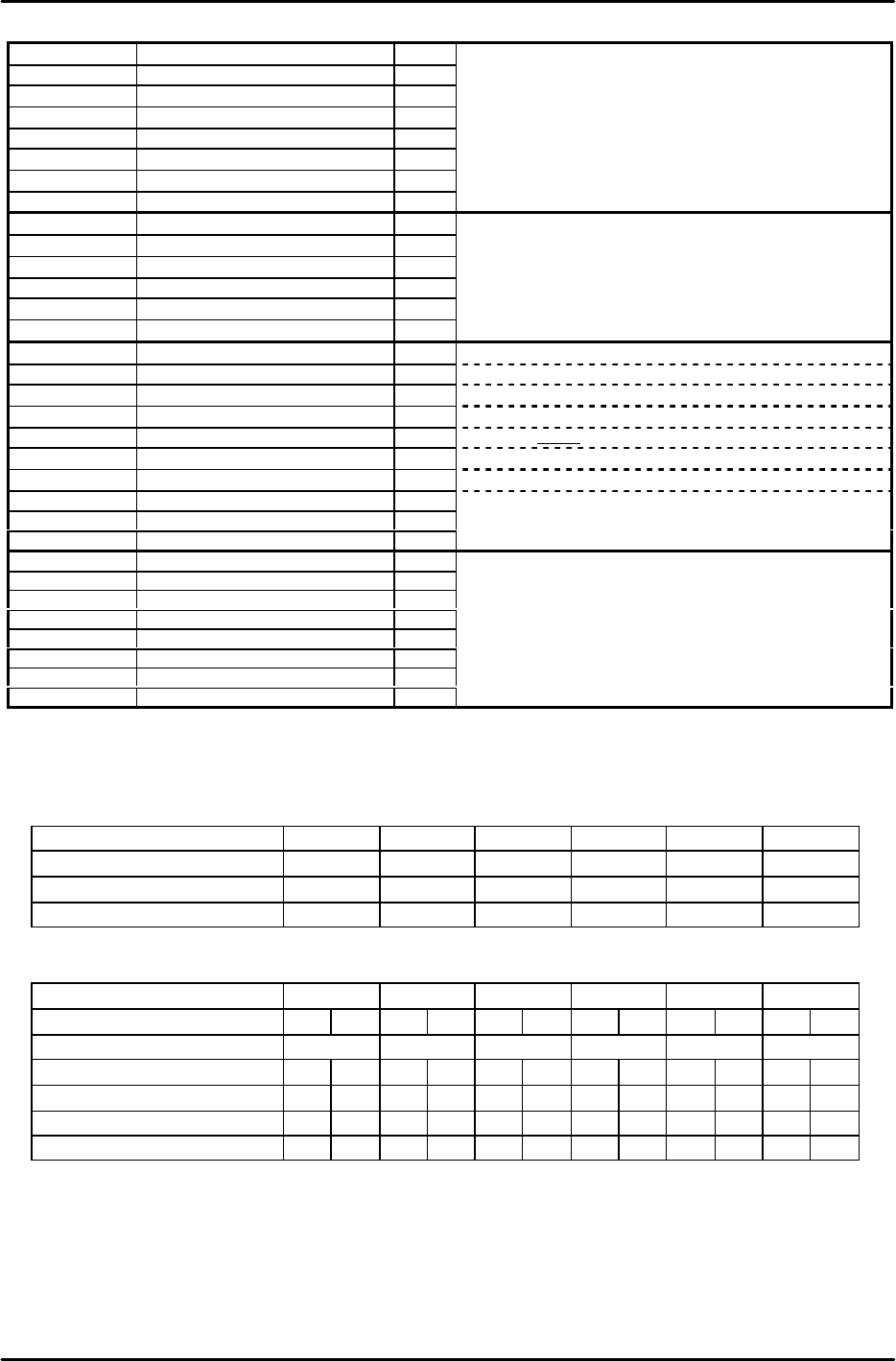
MQ2*FLSS PLM* Front Light Scan Speed 288
MQ2*BLSS PLM* Back Light Scan Speed 288
MQ2*SOPH PLM* Scan Offset Pulse H 2000
MQ2*SOPM PLM* Scan Offset Pulse M 2000
MQ2*SOPL PLM* Scan Offset Pulse L 2000
MQ2*DP Device Pitch 2000
MQ2*APXY Arch Pulse XY
20000
MQ2*AHZ Arch Height Z 1400
MQ2*FNT1 PLM* Feeding On Timer 200
MQ2*FNT2 PLM* Feeding On Timer_2 100
MQ2*FNT3 PLM* Feeding On Timer_3 200
MQ2*FFT1 PLM* Feeding Off Timer 200
MQ2*FFT2 PLM* Feeding Off Timer_2 100
MQ2*FFT3 PLM* Feeding Off Timer_3 200
MQ2*P1~4BP PLM* RS232C Port1~4 BPS 2 9600
MQ2*P1~4DL
PLM* RS232C Port1~4 Data Length
1 8
MQ2*P1~4SB PLM* RS232C Port1~4 Stop Bit 0 1
MQ2*P1~3PA PLM* RS232C Port1~3 Parity 0 NONE
MQ2*P4PA PLM* RS232C Port4 Parity 2 EVEN * Note
MQ2*FPSP PLM* Flux Pump SCU Port 3
MQ2*PPCP PLM* PPC Port 0 Enter "2" at systems with a placing pressure control function.
MQ2*LLLP PLM* LLL Port 3
MQ2*LLUP PLM* LLL Upload Port 1
MQ2*PECW PLM* Parts Eject Conv Width
à
MTU6: M=74 MTU71: M=50 MTU not used =27
MQ2A(1or2)LL0 PLM* Camera(1or2) Level Limit 0
à Camera type 1=100 :2=50 :3=50 :4=0 :6=0 :7=0 :8=0 :9=0
MQ2A(1or2)LL1
PLM* Camera(1or2) Level Limit 1
à
Camera type 1=0
:2=100
:3=100
:4=100
:6=100
:7=100
:8=100
:9=70
MQ2A(1or2)LL2
PLM* Camera(1or2) Level Limit 2
à
Camera type 1=0
:2=100
:3=100
:4=0
:6=0
:7=35
:8
=0
:9=0
MQ2A(1or2)LL3
PLM* Camera(1or2) Level Limit 3
à
Camera type 1=0
:2=100
:3=100
:4=35
:6=0
:7=35
:8=0
:9=0
MQ2A(1or2)DT0
PLM* Camera(qor2) Dev Tol 0
à
Camera type 1=40
:2=10
:3=10
:4=0
:6=0
:7=0
:8=0
:9=0
MQ2A(1or2)DT1
PLM* Camera(qor2) Dev Tol 1
à
Camera type 1=0
:2=10
:3=10
:4=10
:6=10
:7=10
:8=10
:9=10
MQ2A(1or2)DT2
PLM* Camera(qor2) Dev Tol 2
à
Camera type 1=0
:2=10
:3=10
:4=10
:6=0
:7=10
:8=0
:9=0
MQ2A(1or2)DT3
PLM* Camera(qor2) Dev Tol 3
à
Camera type 1=0
:2=10
:3=10
:4=10
:6=0
:7
=10
:8=0
:9=0
Note: "*" indicates the module No. (Attr is A to F, Caption is 1 to 6)
Note 1: Multiplexe Type
0: VSM12 (Up to 12 connector channels for CCD camera connection
1: VSM18 (Up to 18 connector channels for CCD camera connection
2: NON (Multiplexer is not used)
Note 2:
Module No. 1 2 3 4 5 6
Mark Camera MPX ch No. 1 3 5 7 9 11
Parts Camera1 MPX ch No. 2 4 6 8 10 12
Parts Camera2 MPX ch No. 13 14 15 16 17 18
Enter "0" as the parts camera (1 or 2) MPX No. for modules without CCD cameras.
LSO channel numbers are assigned in sequence beginning from "1", with up to 4 numbers being assigned to each LSO.
[Ex] Number assignments would be as shown below for the following: ICM-(CCD CCD)-(CCD CCD)-(CCD LS)-(CCD LS)-(CCD)-(CCD LS)
Module No. 1 2 3 4 5 6
Camera(1or2) Type CCD CCD CCD CCD CCD LS CCD LS CCD LS CCD LS
Mark Camera MPX ch No. 1 3 5 7 9 11
Parts Camera(1or2) MPX ch No. 2 13 4 14 6 0 8 0 10 0 12 0
Parts Camera(1or2) LSO ch No. 0 0 0 0 0 1 0 2 0 3 0 4
Parts Camera(1or2) LSO board No. 0 0 0 0 0 1 0 1 0 1 0 1
Parts Camera(1or2) VP board No. 1 1 1 1 1 1 1 1 1 1 1 1
Note 3: PLM* Machine Status
0: For machines with parts supplied from the front
1: For MOTOROLA special 2-stop conveyor
2: For MOTOROLA special sensor block skip
4: For machines with parts supplied from the rear
8: For flux application after vision processing
16: Part pick-up confirmation sensor
32: For module PCB impact support (V1.3D or newer)
64: TZ axis up/down interlock disabled when MTU7 shuttle is at its advance limit
128: Nozzle size check tolerance of 0.3mm. ("0.15mm" is adopted if not specified.) As a rule, this setting should not be

FK-9F98-07 QP242E Training Text for Service Engineers
6th edition 3. QP242E Initial Adjustment (2) [3/12]
Fuji Machine Mfg. Co., Ltd. Okazaki
SMT Equipment Quality Assurance Dept.
Technical Support Div. Section No.2
3-3
specified. (V1.40 or newer)
256: Enable Operation of the old type sliding remover. (V1.49 or newer)
512: Record the robust trace
2048: Nozzle drop prevention (soft take-off only when picking up tray parts. This setting should be used only for modules which
use single holders with a spring-back amount of 3.5mm.) (V1.80 or newer)
4096: For tray pick-up confirmation function
32768: For modules which use single holders with a spring-back amount of 3.5mm. (V1.80 or newer)
Note 4: Machine Status A
1: F-mark relief command
8: Remote command permission
32: Machine stops after bad mark reading if all placing sequences are skipped. When restarted, operation begins with mark
reading. (V1.80 or newer)
Note 5: Machine Status B
1: Module production continuation (this is different from the independent function. When an error stop occurs, production
continues only at modules which follow the error stop module. Operation is stopped at modules located before the error
stop module.)
2: Idling with vision processing (If this function has been used, be sure it is disabled before shipment.)
4: Nozzle bend measurement function (Usable only for round nozzles at CCD camera with back lighting.)
16: Displays the acquired image during automatic operation (V1.80 or newer)
256: For tray direction (V1.90 or newer)
512: Movement change for package type 5*, 6*(V1.90 or newer)
Note 6: PLM* Module Width
At F4G versions prior to V2.12, with a C/C version prior to V2.01, set as "MQ2*S7:PLM* spare" (spare under PLM*
Nickname). Proper data created at C/C versions prior to V2.01 should be transmitted back to the host first, and then
transmitted to the machine.
Note 7: PLM* Escape Position Z
Old Z-axis Zero Setting : Single Head Module which installed Camera type 7 = 2666 (Others =0)
New Z-axis Zero Setting : All of Module = 2000
* Set PLM2 to 6 in the same manner.
* When changing and then reusing previous Proper data, verify that the all the following values are set to
"0":
Center_Offset_X,Y
Final_Offset_X,Y,Q
Zero_Offset_Q
If an MTU is used, also verify that the "Zero_Offset_TY,TZ" item is set to "0".
2) Start up the machine by [RESET] + [POWER ON]. The following then displays in yellow: PLM Start
Processing, Memory Backup NG, Transmit Proper Value.
3) Transmit the temporary Proper data edited at step 1) above to the machine.
4) After the Proper data is transmitted, the yellow character display clears and "S/W Transmitting"
displays, indicating that the Proper data is automatically being transmitted to each module from the
ICM. When completed, "PCM Parameter" displays, indicating that the parameter data is
automatically being transmitted to each module from the ICM. When all transmissions are
completed, "Reset Start Executed, Turn Power Off" displays in yellow, indicating that the Proper data
transmission operation is completed.
* If the automatic parameter transmission fails, transmit the parameter data as described below.
[3-2] Parameter Transmission Procedure
1) While pressing the [F4] key, turn the power on. This will start up the machine in the mechanical
check mode.
2) In response to the [Max Module No.?] prompt, enter the number of modules being used at the
machine in question. [Number of modules] à [CR].
3) "PLM Start Processing, S/W Transmitting" then displays in yellow. Wait for approximately 5
minutes.
4) Use the following commands to transmit the parameter data to all the modules:
[PARAMETER] à [PRM TRAN ] à [ALL PLMS] à [YES]
* If the [Parameter] screen fails to display, reset the machine (power off), then begin again from step 1
above.
5) The transmission is complete when "Parameter For PLM" displays in yellow and the system returns
to the original screen.
* Thereafter, the mechanical check mode can be used for sensor adjustments, etc., as necessary.