QP-242E 工程师培训手册 (6.0).pdf.pdf - 第86页
FK-9F98-07 QP242E Training Text for Service Engineers 6th edition 9. Reject Parts Conveyor Adjustment & Operation Check [ 2 / 2 ] Fuji Machine Mfg. Co., Ltd. Okazaki SMT Equipment Quality Assurance Dept. T echnical S…
FK-9F98-07 QP242E Training Text for Service Engineers
6th edition 9. Reject Parts Conveyor Adjustment & Operation Check [1/2]
Fuji Machine Mfg. Co., Ltd. Okazaki
SMT Equipment Quality Assurance Dept.
Technical Support Div. Section No.2
9-1
[CHAPTER 9] Reject Parts Conveyor Adjustment
& Operation Check
[9-1]
Prior to Adjusting the Reject Parts Conveyor
There are two types of reject parts conveyors; an L-type (wide) and M-type (narrow).
Furthermore the conveyor is an option and thus all MFUs are not necessarily equipped
with such a conveyor. Check the specification manual or with the Sales department
for the module numbers equipped with a conveyor, the number of conveyors, and the
conveyor type before carrying out work.
Size Belt width Compatible parts
Occupied device
positions
M 33.4 mm 27 ~ 31mm 3
L 78 mm 74 mm 6 (7)
The value in parentheses indicates a conveyor loaded without use of an STU.
The belt width and compatible part size for a reject parts conveyor attached to an MTU6 are both the
same as the data for the L size conveyor.
The belt width of a reject parts conveyor attached to an MTU71 is 54 mm and the compatible part size
is up to 50 mm square.
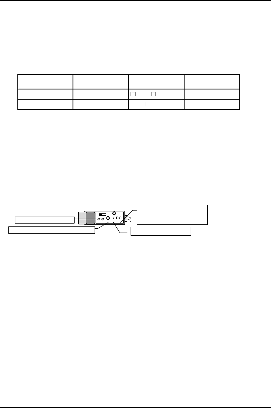
[9-2] Belt Tension Adjustment
Loosen the motor mount bolts to loosen the chain.
Push in on the belt tension adjustment bolt by 18 to 19 mm and pull the conveyor belt tight.
After the belt tension is adjusted use the motor mount bracket to adjust the chain tension.
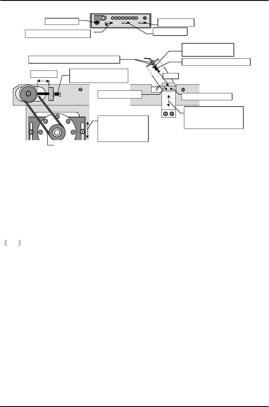
[9-3] Part Check Sensor Adjustment
1) Set the part check sensor located on the bottom of the conveyor as indicated below.
2) Move the sensor bracket to adjust the sensor so that it comes on when a 1 mm part is
loaded on the conveyor and goes off when the part is removed.
[9-4] Large Part Detection Sensor Adjustment
1) Adjust the sensor up and down so that the distance between the tip of the large parts reject sensor
and the top of the conveyor is 35 mm.
2) Loosen the nut on the large parts reject sensor lens mechanism, turn the lens to a position where
the round red dot of light appears clearly on the reject parts conveyor (in focus), and then tighten
the nut.
3) Set the large part detection sensor amp located on the bottom of the conveyor to “D, ON”, “OFF” and
then set to “Unlock”.
4) Press [SET] with no parts on the conveyor.
5) Load a part on the conveyor and then press [SET]. (Auto-adjustment complete)
6) Then after setting to “Lock”, load a part on the conveyor and check again.
OFF
ALM
OUT
SENS.
TIME.
MODE
0.04 5
5
For reject detection set the
MODE to “5”.
For the TZ-axis set to “1”.
Set the timer to “0.04”.
Set the sensor volume to “Max”.
Set to “ALM.OFF”.
KEYENCE
FK-9F98-07 QP242E Training Text for Service Engineers
6th edition 9. Reject Parts Conveyor Adjustment & Operation Check [2/2]
Fuji Machine Mfg. Co., Ltd. Okazaki
SMT Equipment Quality Assurance Dept.
Technical Support Div. Section No.2
9-2
[9-5] Operation Check of Air Pencil
Put inside a spare part and carry out an operation check of the air pencil.
[9-6] Input of Proper Data Setting for PLM? MFU Parts Eject Conveyor D no
When an MFU is equipped with a reject parts conveyor the device number at which it is installed
must be set. Specify the load number setting from the customer or if there are no other options
loaded then set the left end of the MFU.
If this item is set to “0” the MFU will be handled as having no reject parts conveyor and all NG
parts will be discarded in the reject parts box.
Retransmit the Proper data after making this setting.
【
9-7
】
Operation Check
Transmit a program to the machine and carry out an operation check of the reject parts conveyor.
SET
KEYENCE FS-
D ,ONL ,ONOFFOF
LOO
LEVEL OU
Set to
“D
,ON”
.
Set to “OFF”.
Set to “Lock” or “Unlock”.
Set button
Chain
18~19mm Conveyor belt tension
adjustment bolt
Error conveyor
Move the motor
mount bracket up
and down to adjust
the chain tension.
Move up and down to
adjust the part check
sensor
35mm
Parts check sensor
Top of conveyor
Large part detection sensor
Loosen this nut and adjust to 35
mm.
Loosen this nut to
adjust the focus.

FK-9F98-07 QP242E Training Text for Service Engineers
6th edition 10. STU Adjustment & Operation Check [1/8]
Fuji Machine Mfg. Co., Ltd. Okazaki
SMT Equipment Quality Assurance Dept.
Technical Support Div. Section No.2
10-1
[CHAPTER 10]
STU Adjustment & Operation Check
[10-1] Prior to Adjusting the STU
STU-1 Specifications
Number of part types : 1 type per unit
Tray size : 100 x 150 mm ~ 150 x 330 mm
Tray stacking height : 4 ~ 50 mm
Max Empty Tray Weight : 240 g/tray
Occupied devices : 9 devices
Number of units that can be loaded: MFU-5 1 (0) MFU-58 2 (1)
- The values in parentheses indicate the number of STUs that can
be loaded on an MFU when a 2-camera system is used.
STU-2 Specifications
Number of part types : 1 type per unit
Tray size : 50 x 50 mm ~ 102 x 102 mm
Tray stacking height : 4 ~ 50 mm
Max Empty Tray Weight : 240 g/tray
Occupied devices : 7 devices
Number of units that can be loaded: MFU-5 2 MFU-58 4
- There are no restrictions when a 2-camera system is used.
- The STU able to stack trays and for this purpose is equipped with a unit to raise trays and a tray
remover.
- Trays are always positioned with a top surface reference using the positioning sensor. As a result
part pickup using the pickup nozzle does not have to take into account such things as the part
height, tray thickness, and number of trays depending on the pickup nozzle.
- Since STU units can be loaded on an MFU it is possible for a mix of STU and IP-type feeders to be
loaded on a module. However, it is not possible to load two different types of STUs on the same
module since this would create two STU mechanical standards.
- Since there is spacing (3 device positions) on both sides of the STU to avoid interference with IP
feeders, it is recommended that the STU be loaded on the left side of the MFU and that an
accompanying reject parts conveyor be loaded on the right side of the STU.
- An independent air source is required on the STU.