QP-242E 工程师培训手册 (6.0).pdf.pdf - 第94页
FK-9F98-07 QP242E Training Text for Service Engineers 6th edition 10. STU Adjustment & Operation Check [ 8 /8] Fuji Machine Mfg. Co., Ltd. Okazaki SMT Equipment Quality Assurance Dept. Technical Support Div. Section …
FK-9F98-07 QP242E Training Text for Service Engineers
6th edition 10. STU Adjustment & Operation Check [7/8]
Fuji Machine Mfg. Co., Ltd. Okazaki
SMT Equipment Quality Assurance Dept.
Technical Support Div. Section No.2
10-7
MFU-58 STU-1
Reject parts
conveyor(M)
Reject parts
conveyor (L)
Feeder
1~9 10~12 None 13~31
1~9 None None 13~31
1-load
1~9 None 10~15 16~31
1~9,10~18 19~21 None 22~31
1~9,10~18 None None 22~31
Device
No.
2 -load
1~9,10~18 None 19~25 26~31
MFU-58 STU-2
Reject parts
conveyor(M)
Feeder
1~7,8~14,15~21 22~24 25~31
1~7,8~14,15~21 None 22~31
1~7,8~14,15~21,22~28 29~31 None
Device
No.
1~7,8~14,15~21,22~28 None 29~31
Note: * When an STU-1 or STU-2 is used without installing a reject parts conveyor,
interference space is required as shown in the following examples so do not set
feeders in these positions. If a feeder is set in one of these device positions the
head
and feeder will collide when the STU part is picked.
Example:
When an STU-1 (D1 ~ D9) is set : D10 ~ D12
When one STU-2 (D1 ~ D7) is set : D8 ~ D10
When two STU-2 units (D1 ~ D7, D8 ~ D14) are set : D15 ~ D17
* An STU-1 and STU-2 cannot be loaded on the same MFU.
* When an STU is installed at device positions other than those given in the
examples above, the number of occupied device positions may increase depending
on the unit that is set adjacent to the STU.
[10-17]
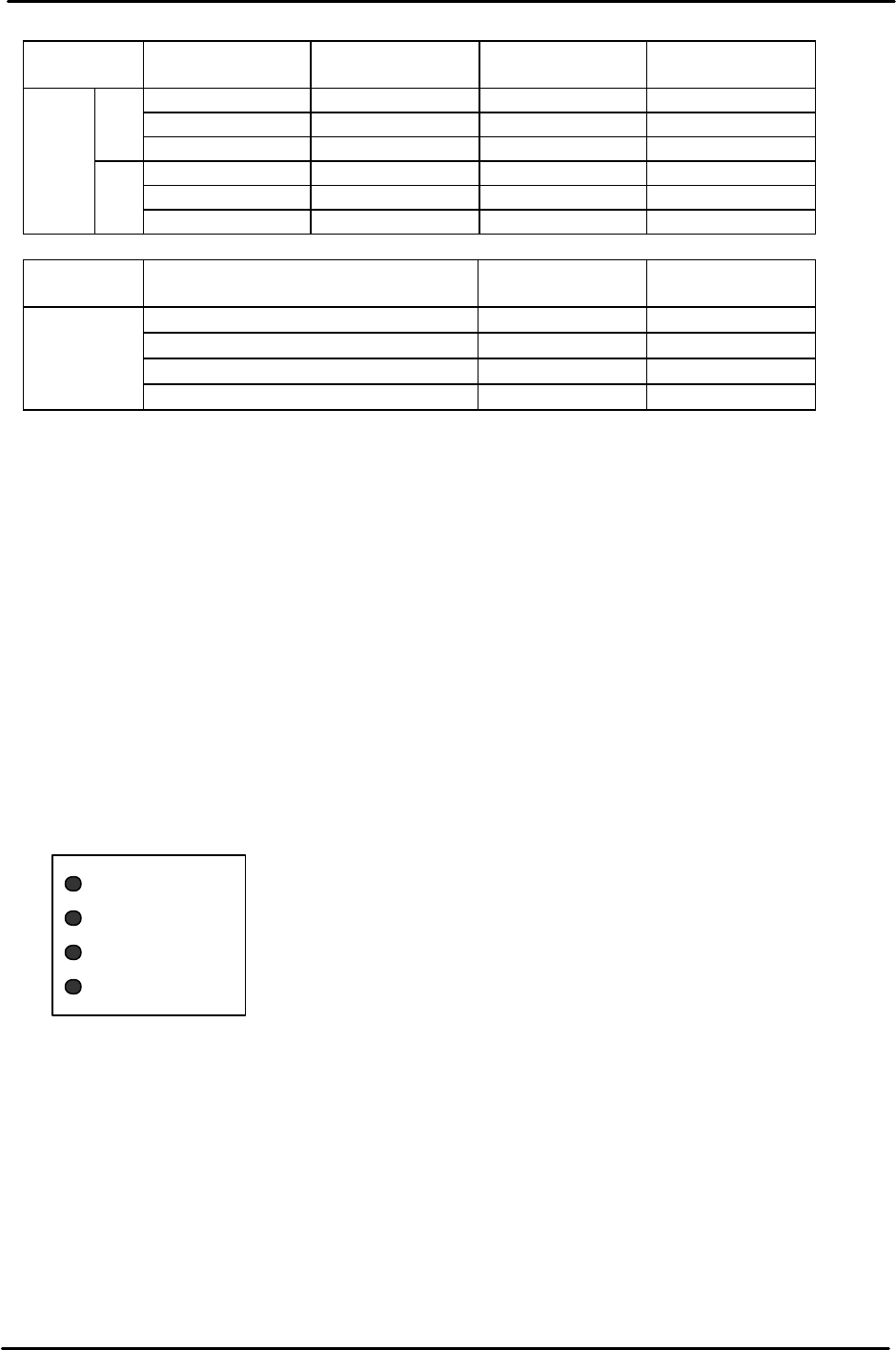
STU Rear LED Display
There are LEDs on the rear of the STU to notify the operator of STU alarms, when to supply trays
to set in the STU and when the empty tray eject box is full. Use the explanation for each of the LED
displays given below as a reference.
[POWER]: Indicates that power is being supplied to the STU.
[ALARM]: The contents of the alarm are indicated by the number of times the connected LED
flashes.
POWER
ALARM
NO TRAY
TRAY FULL

FK-9F98-07 QP242E Training Text for Service Engineers
6th edition 10. STU Adjustment & Operation Check [8/8]
Fuji Machine Mfg. Co., Ltd. Okazaki
SMT Equipment Quality Assurance Dept.
Technical Support Div. Section No.2
10-8
Number
of flashes
Contents Details
1
Sequencer
alarm
Trouble with the sequencer
2
Cycle time
expired
Tray positioning or the tray eject operation did not finish
within 60 seconds.
3 Tray eject alarm
The descent of the empty tray could not be verified when
discharged or the empty tray eject box has become full.
4 Tray add alarm Too many trays have been added.
Remover SOL
alarm
The remover did not arrive at the forward limit (retract
limit) when the remover was advanced (retracted).
Vacuum OFF
defect
The vacuum did not cut off even though the remover is at
the retract limit.
5
Remover LS
alarm
The remover forward limit and retract limit sensors are
both on.
[NO TRAY]: There are no tray parts. Supply parts.
[TRAY FULL]: The empty tray eject box is full. Remove the empty trays in the box.

FK-9F98-07 QP242E Training Text for Service Engineers
6th edition 11. Coplanarity Check Adjustment & Operation Check [1/4]
Fuji Machine Mfg. Co., Ltd. Okazaki
SMT Equipment Quality Assurance Dept.
Technical Support Div. Section No.2
11-1
[CHAPTER 11] Coplanarity Check Adjustment & Operation Check
[11-1] Prior to Coplanarity Check (Bent Lead Detection) Adjustment
- A bent lead detection sensor is installed on top of the base of the placement module using a
laser transmission system.
- Equipped with an inspection function for detecting bent leads that is governed by JEDEC
standards.
- Applicable parts Parts with leads in four directions (QFP, VQFP)
Parts with leads in two directions (SOIC, VSOP, TSOP)
However, the ends of the leads of parts in the picked status must extend beyond the
diameter of the nozzle by more than 3 mm.
- Measurement accuracy : ± 0.01 mm
- Tolerance value input range : 20 ~ 3,000 um
- Measurement time : Approximately 3.5 seconds/ 4-directions
When bent leads are detected on a specified part, the
measurement time is added to the placement time.
【
11-2
】
Proper Data Measurement & Transmission
- Enter the values listed below in the appropriate data items and reboot the machine after the
Proper data is transmitted.
- The question mark “?” displayed in the Caption items represents the relevant module
number.
- Enter the appropriate value (front supply/rear supply) for Coplanarity X and Y.
- At present a negative value cannot be entered in F4G for the Coplanarity Z value.
(The value will display as a negative value on the machine.)
- The values for Coplanarity X, Y, and Z are temporary input values until automatic
measurement is carried out. These values will change at that time.
[Caption] [Value] [Record] <The following are in order
according to the module number.>
PLM? Coplanarity Check 1(Yes) 163, 178, 193, 208, 223, 238
PLM? Coplanarity LLL Qty 0(Not used) 761,1194,1627,2060,2493,2926
PLM? Coplanarity Calculation 0(Last) 762,1195,1628,2061,2494,2927
PLM? Coplanarity Recovery Time 1 763,1196,1629,2062,2495,2928
PLM? Coplanarity Z Correction 0(Not used) 764,1197,1630,2063,2496,2929
PLM? Coplanarity Recovery Offset 0 765,1198,1631,2064,2497,2930
PLM? Coplanarity LLL Y Depth 0(Not used) 766,1199,1632,2065,2498,2931
PLM? Coplanarity X -184000/184000 767,1200,1633,2066,2499,2932
PLM? Coplanarity Y -218000/218000 768,1201,1634,2067,2500,2933
PLM? Coplanarity Z 4294957400 769,1202,1635,2068,2501,2934
PLM? Coplanarity Y Speed 347(34.7%) 770,1203,1636,2069,2502,2935
PLM? Coplanarity Data Upload 0(No) 771,1204,1637,2070,2503,2936
PLM? LLL Port 3 896,1329,1762,2195,2628,3061
PLM? LLL Upload port 1 897,1330,1763,2196,2629,3062
[11-3] Jig Preparation
In addition to a dial gauge the following jigs are also needed for coplanarity check adjustment
work and automatic measurement.
1) Jig plate : BHPJ-0570 (28 mm square, t= 0.7 mm)
2) Measurement nozzle : Specialized nozzles are used that depend on the head type.
ABHPJ-6430 (single type)
ABHPJ-6440 (index type)
[11-4] Positioning Key Parallel Adjustment
Attach the dial gauge on the placement head and adjust the key that has been installed on the
top of the base so that it is parallel to the X-axis within 0.01 mm.