QP-242E 工程师培训手册 (6.0).pdf.pdf - 第41页
FK-9F98-07 QP242E Training Text for Service Engineers 6th edition 5. Before Beginning the Proper Data Measurements [ 6 / 6 ] Fuji Machine Mfg. Co., Ltd. Okazaki SMT Equipment Quality Assurance Dept. Technical Support Div…
FK-9F98-07 QP242E Training Text for Service Engineers
6th edition 5. Before Beginning the Proper Data Measurements [5/6]
Fuji Machine Mfg. Co., Ltd. Okazaki
SMT Equipment Quality Assurance Dept.
Technical Support Div. Section No.2
5-5
3) For camera type 6 (line scan camera), with front lighting:
* When the "Y006 F.LIGHT 1" or "Y007 F.LIGHT 2" I/O is on, the shutter opens and the halogen
turns on. (Operation is the same for either "F.LIGHT 1" or "F.LIGHT 2".)The halogen lamp does
not light when the "Y00B F.LIGHT B" I/O is switched on.
* When the "Y006 F.LIGHT 1" I/O is on, the shutter opens and the bottom halogen lamp turns on.
When the "Y007 F.LIGHT 1" I/O is on, the shutter opens and the top halogen lamp turns on.
When the "Y00B F.LIGHT B" I/O is on, the ring light (fluorescent light) turns on.
* After verifying that the dip switch is at the upper position (MANUAL), set the halogen lamp
adjusting volume to "2.8".
4) For camera type 7 (line scan camera), with front lighting:
* When the “Y006 F.LIGHT 1” I/O is on, the shutter opens and the bottom halogen lamp turns on.
When the “Y007F. LIGHT 1” I/O is on, the shutter opens and the halogen lamp turns on.
When the “Y00B F. LIGHT B” I/O is on, the ring light (fluorescent light) turns on.
* After verifying that the dip switch is at the upper position (MANUAL), set the halogen lamp
adjusting volume to “1.8”.
* After verifying that the exchange switch is at the bottom position (MANUAL), set the upper halogen
ring light adjusting volume to 8 (MAX is 10).(Exchange switch is on back upper.)
5) When creating programs, be sure to select the Camera_Lighting (in Part Data) which is
appropriate for the part which is to be placed.
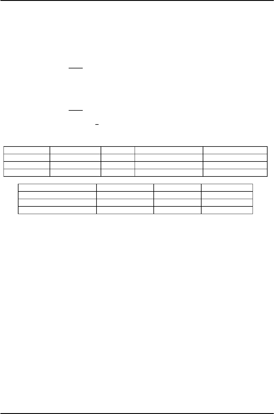
Camera types 2 and 3 (CCD cameras)
Applicable part Top light Bottom light (inner) Bottom light (outer)
Front_Light_A Parts with leads ON OFF ON
Front_Light_B Black BGA ON OFF OFF
Front_Light_AB White BGA OFF ON ON
Camera type 4 (line scan camera)
Applicable part Halogen light Ring light
Front_Light_A Parts with leads 70% ON
Front_Light_B Black BGA Full open ON
Front_Light_AB White BGA Full open OFF

FK-9F98-07 QP242E Training Text for Service Engineers
6th edition 5. Before Beginning the Proper Data Measurements [6/6]
Fuji Machine Mfg. Co., Ltd. Okazaki
SMT Equipment Quality Assurance Dept.
Technical Support Div. Section No.2
5-6
*****This page does not contain any contents.
FK-9F98-07 QP242E Schooling Text for Service Engineer
6th edition 6. Proper Data Measurement [1/20]
Fuji Machine Mfg. Co., Ltd. Okazaki
SMT Equipment Quality Assurance Dept.
Technical Support Div. Section No.2
6-1
[CHAPTER 6] Proper Data Measurement
Notes regarding vision processing board handling:
1. Never unplug or plug in cables, etc., when the power supply for the vision processing board and
monitor is on. Such actions can damage the vision processing board.
2. Always wear a wrist-band when touching the vision processing board with hands in order to
prevent IC damage caused by static.
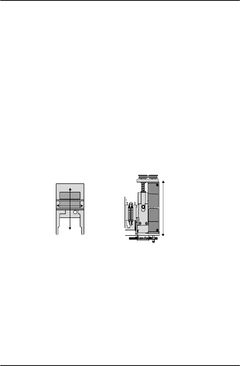
[6-1] Max, Min Limit Position
Note: The plus/minus symbols shown with the X,Y axis servo counter values are
reversed for rear part-supply machines.
1) Display the [Max/Min] screen. At the [X] [Y] [Z] display items, select [X].
[MAX LIMIT] [MIN LIMIT] then displays.
2) Turn off the 200V power supply, release the servo lock, and move the head to the machine’s
right-side mechanical stopper for the [MAX LIMIT], and to the left-side mechanical stopper
for the [MIN LIMIT].
* Note that the MAX and MIN directions are different at rear part-supply machines.
See the figure below.
3) With the head pressed against the stopper, press [MAX LIMIT] or [MIN LIMIT], then press
[SET] and enter the counter value for this position directly to the machine.
4) Measure the Y-axis and Z-axis MAX and MIN limits in the same manner.
* For both the Y-axis Min_Limit_MFU and MTU, enter the value which was measured at the
mechanical stopper position.
X-axis Max
Limit (Min
Limit at rear
load type m/c)
X-axis Min Limit
(Max Limit at rear
load type m/c)
Y-axis Max Limit (Min Limit
at rear part-supply machines)
Y-axis Min Limit (Max Limit
at rear load type m/c)
Z-axis Max Limit
Z-axis Min Limit