QP-242E 工程师培训手册 (6.0).pdf.pdf - 第115页
FK-9F98-07 QP242E Training Text for Service Engineers 6th edition 13. MTU 71E Adjustment [ 13 /24] Fuji Machine Mfg. Co., Ltd. Okazaki SMT Equipment Quality Assurance Dept. Technical Support Div. Section No.2 13- 13 [1 3…
FK-9F98-07 QP242E Training Text for Service Engineers
6th edition 13. MTU 71E Adjustment [12/24]
Fuji Machine Mfg. Co., Ltd. Okazaki
SMT Equipment Quality Assurance Dept.
Technical Support Div. Section No.2
13-12
[13-33] Prior to Connecting the MTU71E
- Cable connections should be made with the power turned off.
- Connect the MTU7 unit to the machine in the zero set complete status with a magazine in the
standby status, with the TZ-axis moved to 0 pulses via inching and with the TY-axis in the
standby status at the forward limit.
- Once the unit is joined to the machine do not turn off the power until measurement of
Original_Position_TY is completed. If after the unit is connected to the machine the power
is cut and zero set is performed again there is a danger of damage resulting from contact
between the shuttle jaw and the tray holder.
Note: When MTU detachment is carried out over the course of installation or adjustment
work, always be sure that the TZ-axis position is lowered to 0 pulses beforehand using
magazine standby or the inching operation.
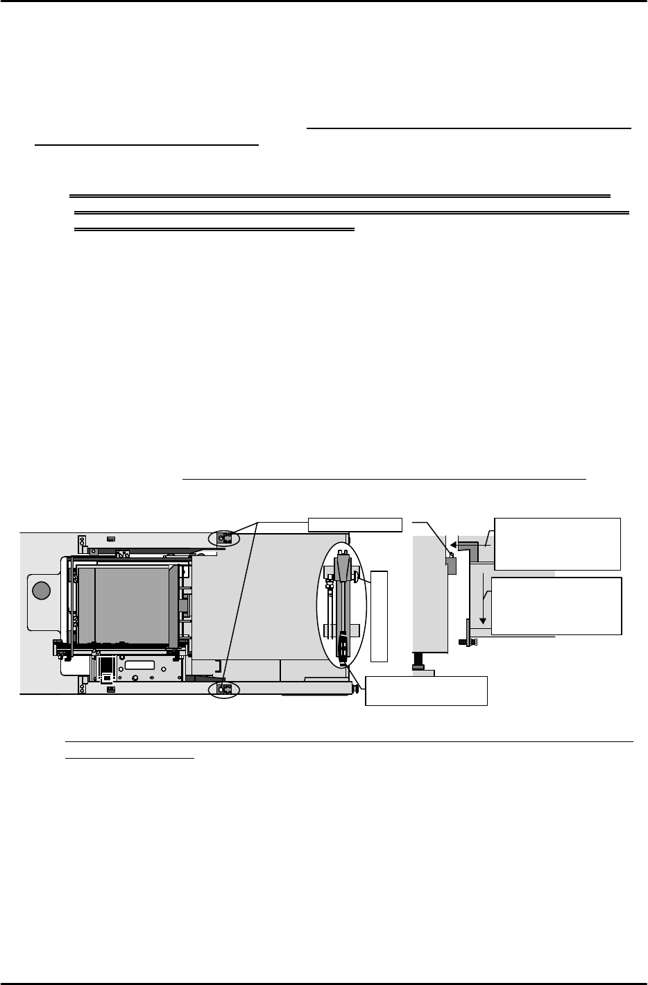
[13-34] MTU71E Connection
1) Use the hydraulic jack on the bottom of the safety door to raise the machine to a height at
which the lower surface of the positioning blocks on the inside of the MTU71E do not make
contact with the tips of the positioning pins on the machine.
2) Carefully move the MTU71E to the machine connection position checking that there is no
interference with the connecting cables or other parts of the unit and then align the
positioning blocks on the inside of the MTU71E with the positioning pins on the machine
side.
3) After this is completed, loosen the hydraulic jack valve to slowly lower the machine and
connect.
4) Verify that there is no gap between the top and bottom blocks and the contact surface and
check that the unit fits perfectly.
(Use a feeler gauge to confirm that the gap is within 0.03 mm.)
Note: If the bolt for adjusting the angle of orientation is loosened by mistake, adjustment must
be performed again.
MTU7
Loosen the air jack to
lower the machine
and connect the MTU
to the machine.
Loosen to lower
M/C
Leveling bolt
Raise the machine to
a height where there
is no interference
with the pins.
M/C
Positioning pins
Move the lever up
and down to raise.
Hydraulic jack
FK-9F98-07 QP242E Training Text for Service Engineers
6th edition 13. MTU 71E Adjustment [13/24]
Fuji Machine Mfg. Co., Ltd. Okazaki
SMT Equipment Quality Assurance Dept.
Technical Support Div. Section No.2
13-13
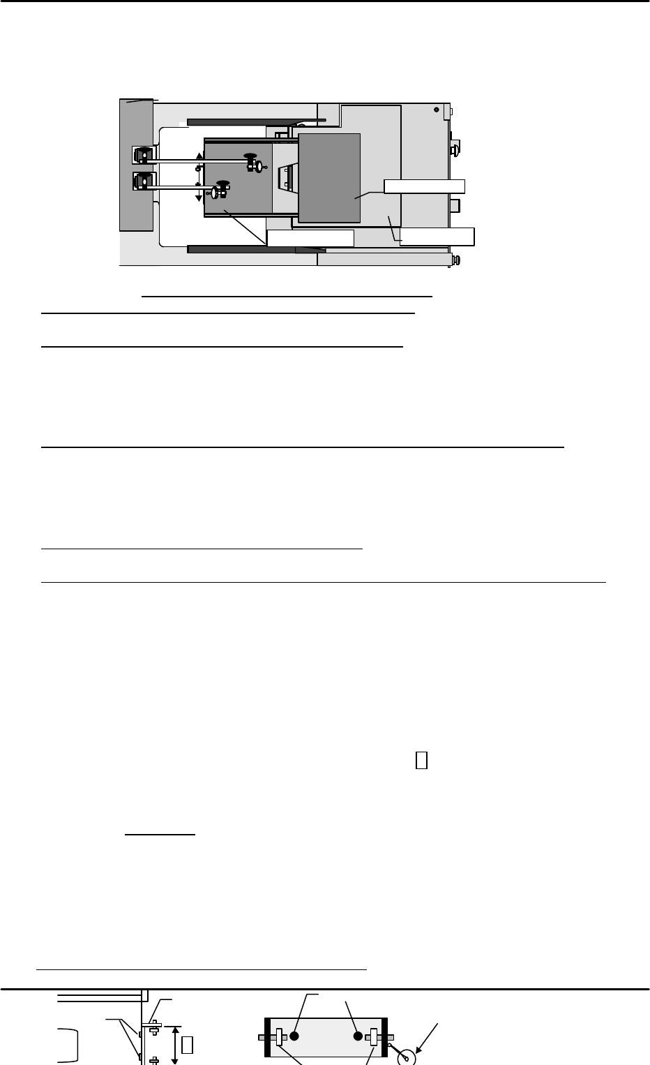
[13-35 ] Tray Holder Levelness and Perpendicularity Adjustment
With the tray holders in the set status, slide each tray holder plate in order towards the
machine. Use a dial gauge to provisionally measure the degree of levelness and
perpendicularity of the tray holder in relation to the machine base.
1) Levelness (1 ~ 9) Tolerance: All tray holders within +/- 0.8mm)
* If the degree of levelness is within the allowable tolerance
Level adjustment is unnecessary. Proceed to perpendicular measurement.
* If the front to back angle of orientation is raised in front
Loosen the angle adjustment bolt on the bottom of the unit to bring the front and back
measurement values within tolerance. (The front and back values should be adjusted as
close to zero as possible.) Furthermore, since the levelness of the tray holder extracted here
is taken into account, ignore the provisional level obtained in the previous process and
proceed with adjustment. The same also applies to the cases mentioned hereafter.
* If the left to right angle of orientation is not within the allowable tolerance range
Adjust the levelness until it is within the allowable tolerance by inserting spacers between
the ball screws on the left and right front side.
Once the levelness falls within the allowable tolerance range, proceed to the adjustment of
perpendicularity.
2) Perpendicularity (10 ~ 11) Tolerance: 0~ +/- 0.3 mm
* If perpendicular measurement is within tolerance
Perpendicular adjustment is unnecessary.
* If perpendicularity of all holders is tilted in the same direction and not within tolerance
Loosen the angle adjustment bolt on the bottom of the unit to free the unit. Loosen the
MTU71E position pin block lock bolts and fine adjust the installation position of the block so
that the perpendicularity falls within tolerance. After adjustment is completed, tighten the
angle adjustment bolt on the bottom of the unit again to adjust the level in the front to back
direction to the same value as adjusted in the previous process. Lastly check the
perpendicular measurement once again.
3) Carry out level and perpendicular measurement of the trays on all ten levels to verify that all
are within the allowable tolerances.
[13-36 ] Tray Eject Bracket Width & TZ-axis Perpendicularity Check
Verify that the width of the eject bracket (inside of bracket A) on all trays is 91.6mm (+/- 0.3
mm). If the width is not within this range then correct it. Next, set the dial gauge from the
machine on the bearing reference side, move the tray up and down and measure the
perpendicularity. Loosen the mounting bolts and adjust so that the perpendicularity of all
levels is within +/- 0.1 mm.
* Be careful that the bracket is not tilted at this time.
M/C
Base
①
④
⑦
②
⑤
⑧
③
⑥
⑨
Top of rack
Base plate
⑩
⑪
Tray holder
Use the machine end as a reference to measure perpendicularity.
A
Bearing reference side
Mounting bolts
Mounting bolts
Move the tray up and down and loosen the
mounting bolts to adjust so that all levels are
within +/- 0.1 mm of being perpendicular
.。
FK-9F98-07 QP242E Training Text for Service Engineers
6th edition 13. MTU 71E Adjustment [14/24]
Fuji Machine Mfg. Co., Ltd. Okazaki
SMT Equipment Quality Assurance Dept.
Technical Support Div. Section No.2
13-14
[
13-37] TY Cam Clamp Bracket Adjustment
Loosen the TY cam clamp bracket and adjust so that it can pass through the center of the eject
bracket adjusted in the previous section, [15-32]. After adjustment is finished move the tray up
and down to verify that there is no interference.
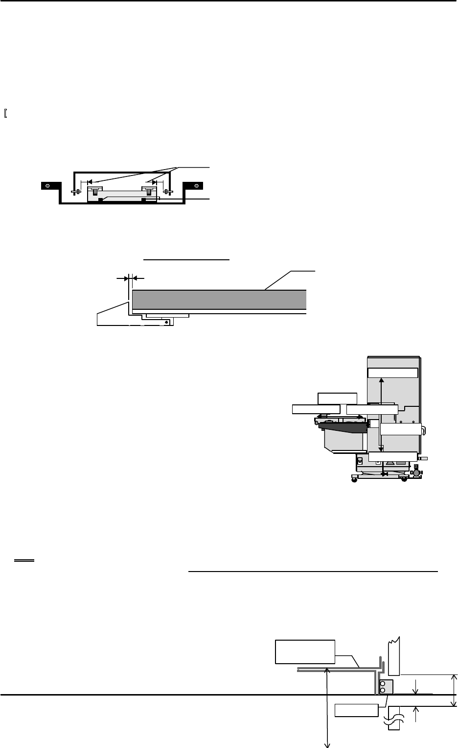
[13-38 ] Tray Holder Lock Adjustment
After the tray is set, adjust so that the gap between the lock mounted on the underside of the
plate and the tray holder is 0.3 mm +/- 0.1 mm.
[13-39 ] Max, Min_Limit_Position
1) Select [PROPER], [Max/Min], and [TY] or [TZ] and
when each axis reaches the negative side or positive
side mechanical stopper position, press [SET] to
automatically enter the Proper data.
2) The [Min_Limit] and [Max_Limit] direction of each axis
is depicted in the figure below.
[13-40 ] Original_Position_TZ
1) Move the TZ-axis via inching so that device number 101 is at the discharge position and then
eject the tray at device number 101. Then inch the TZ-axis to a position where the distance
from the QP2 machine base surface to the top of the device 101 tray holder is 157 mm +/- 0.5
mm.
Note: When the TZ-axis is operated via inching it will not move if the shuttle retract limit
sensor is not on. Also note that the tray cover and tray holder axis will come in contact if
the TZ-axis is inched prior to TZ-axis interlock sensor adjustment and if it is inched when
the shuttle has discharged the tray holder from the tray rack. Exercise due caution if the
axis must be moved during adjustment.
2) In this position select [PROPER], [DEVICE], [ORG.POS.TZ], and [SET] from the operation
monitor to automatically enter the Proper data.
[13-41 ] Guide Rail Adjustment
1) From the Original_Position_TZ position, adjust
the distance between the bottom surface of the
Stopper
157mm
±
0.5
mm
28mm
3.7
~
4.0mm
Tray holder
D101
Org.Pos.TZ
Min Limit
TY
-axis
Min Limit
TZ-axis
Max Limit
Max Limit
Loosen the bolts and adjust so that the gap is equally
distributed on the left and right.
Loosen these bolts to adjust.
0.3mm ± 0.1
Tray holder