QP-242E 工程师培训手册 (6.0).pdf.pdf - 第121页
FK-9F98-07 QP242E Training Text for Service Engineers 6th edition 13. MTU 71E Adjustment [ 19 /24] Fuji Machine Mfg. Co., Ltd. Okazaki SMT Equipment Quality Assurance Dept. Technical Support Div. Section No.2 13- 19 [13 …
FK-9F98-07 QP242E Training Text for Service Engineers
6th edition 13. MTU 71E Adjustment [18/24]
Fuji Machine Mfg. Co., Ltd. Okazaki
SMT Equipment Quality Assurance Dept.
Technical Support Div. Section No.2
13-18
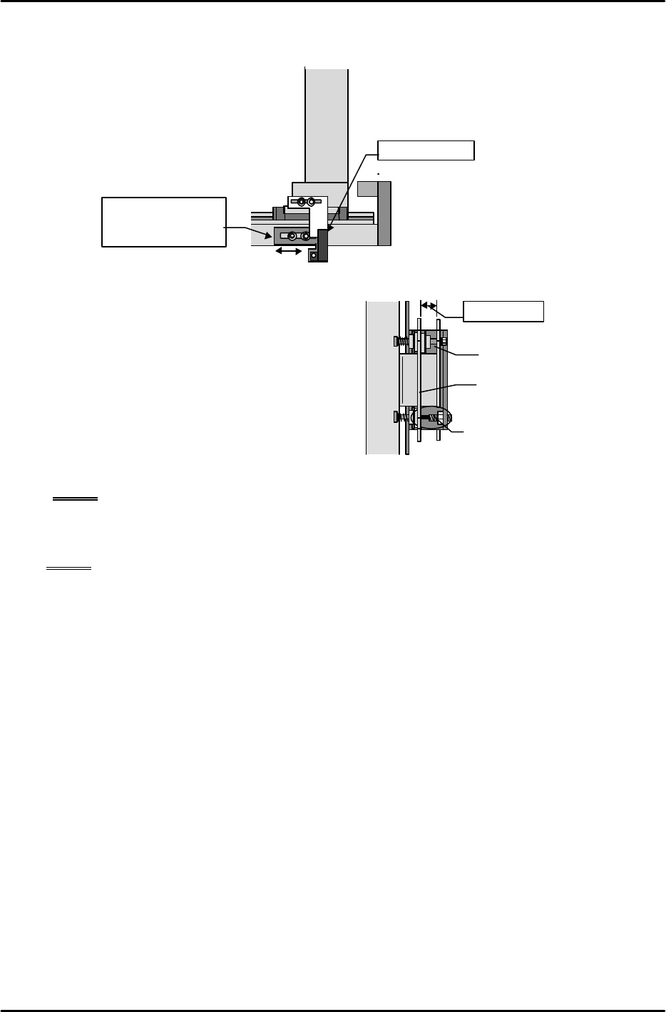
[13-48] TY-axis Retract Limit (Escape Position) Sensor Adjustment
At the Original_Position_TY position adjust the sensor mounting bracket position so that the
end surface of the dog and sensor are aligned along the same plane.
[13-49 ] Shuttle Jaw Opening Adjustment
1) Move the TY-axis to the forward limit and
return the jaw opening adjustment stoppers
that were removed earlier to their original
positions. Align so that the length of the
stoppers is approximately 10mm.
2) Move the TY-axis back to the
Original_Position_TY position again. Adjust
the length of the stoppers and open the
moveable claw of the jaw to a position where
the gap between the inside of the stationary
claw and the outside of the moveable claw is between 9.5 and 10.5 mm.
NOTE: Carefully adjust the balance of both stoppers.
3) Verify that the dog does not separate from the retract limit sensor as a result of the spring
force of the shuttle jaw even when the emergency stop status is activated at the
Original_Position_TY position.
NOTE: If the TY-axis moves away from the retract limit sensor as a result of an emergency
stop it is possible that the cam jaw contact is weak. However, care should be
exercised since if the contact is too strong this will increase the friction when a tray
is stored and lead to tray vibration.
4) Once adjustment is completed verify that there is no interference when the TZ-axis is moved
up and down at the Original_Position_TY position.
Shuttle
bar
Original_Position_TY position
Same plane
Move the sensor
bracket to adjust
Shuttle bar
10 mm gap
Adjust the stopper bolt at the
Original,TY posiiton
Shuttle jaw stationary side
Shuttle jaw secondary side
FK-9F98-07 QP242E Training Text for Service Engineers
6th edition 13. MTU 71E Adjustment [19/24]
Fuji Machine Mfg. Co., Ltd. Okazaki
SMT Equipment Quality Assurance Dept.
Technical Support Div. Section No.2
13-19
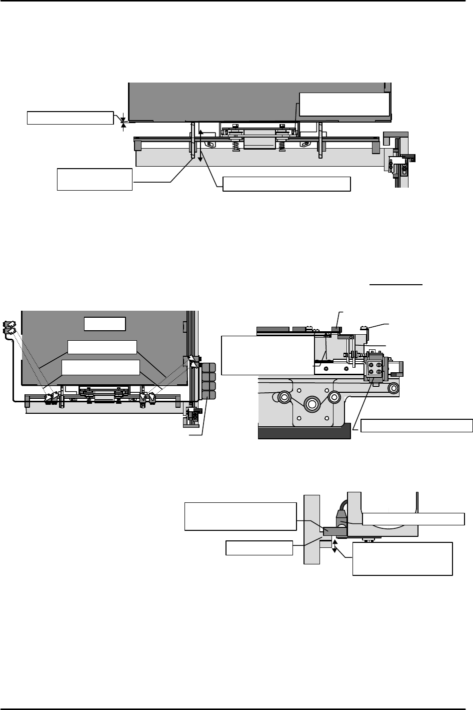
[13-50]
Tray Pusher Installation
1) With the shuttle jaw clamping the guide rollers, pull the tray plate forward and reattach the
blue duracon tray pusher before beginning adjustment.
2) While verifying that the guide rollers are securely clamped by the shuttle jaw, adjust so that
the space between the end of the tray plate and the tray pusher is between 0 and 0.5 mm.
[13-51] Tray Positioning Sensor Adjustment
Move the TZ-axis to the Original_Position_TZ height via inching and pull device position
number 101 to the forward limit position. Raise the TZ-axis another 3,500 pulses (35 mm)
from this position and then move the sensor bracket up and down to adjust the position so that
the tray positioning sensors at both corners of the tray plate detect the top of the tray plate.
Once adjustment is complete, reconfirm that the sensors respond within ± 30 pulses of the
3,500-pulse (35 mm) position.
[13-52 ] TZ-axis Interlock (Shuttle Forward Limit) Sensor Adjustment
1) With the device number 101 tray plate in the empty status, move the shuttle to the forward
limit and slowly inch the TZ-
axis to the position where the
tray add sensors come on.
2) Adjust the outside dog up and
down so that the interlock
sensor gets blocked and also
the tray add sensor turns ON
at the same time.
(The interlock sensor become
OFF because of Nozzle change.)
Space of 0 to 0.5 mm
Shuttle bar
Tray Plate
Move the tray pusher to adjust
Guide rollers should
be tightly clamped
Tray pusher
(blue duracon)
Outside dog
Comes on at the same time
as the tray add sensors
Move the outside dog up
and down to adjust
TZ-axis interlock sensor
Shuttle forward limit position
Tray plate
Sensor amp
Tray plate
Sensor
Shuttle jaw
Shuttle forward limit position
Tray add sensors
Positioning sensors
Positioning sensors
come on in a position
3,500 pulses above
Original_Position_TZ.
FK-9F98-07 QP242E Training Text for Service Engineers
6th edition 13. MTU 71E Adjustment [20/24]
Fuji Machine Mfg. Co., Ltd. Okazaki
SMT Equipment Quality Assurance Dept.
Technical Support Div. Section No.2
13-20
[13-53 ] Operation Check of the Tray Check Sensors
1) Empty tray detection check
With nothing loaded on the tray plate use the following command operation to verify that
operation is halted by a "No tray found" error (last stacked tray ejected): [SET], [POSITION],
specify module number, [MTU], [MOVE Dno], [101], hit return and then press START.
2) Operation check of tray add sensors
Set a 4 mm tray on the device position number 101 tray plate and execute the [MOVE Dno]
command to carry out the positioning operation. After positioning finishes, add another 4
mm tray to verify that the tray add sensors come on correctly. Execute the [MOVE Dno]
command again, lower the TZ-axis and if the positioning operation is carried out this means
the sensors are functioning properly.
3) Verify that the above operation is working properly for all devices from device position 101
through 120.
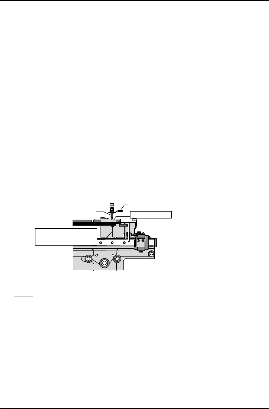
[13-54 ] Original_Position_Z1,Z2 Calibration
1) Set the nozzle jig.
2) Set the measurement jig at device position 101, execute the [MOVE Dno] command, and
carry out TZ-axis positioning.
3) Set a dial gauge on the Z-axis, lower the axis, and then set a dial gauge on the nozzle jig
luminescent disk at the position where the tip of the nozzle jig makes contact with the top of
the measurement jig.
4) Slowly raise the Z-axis to find the position at which the dial gauge needle begins moving.
5) The position at this time becomes Original_Position_Z1. Use the following command
operation to automatically enter the Proper data for this item: [PROPER], [DEVICE],
[Org.Pos.Z], [Org.Pos.Z1], and press SET.
6) Next, set the measurement jig at device position 102, use the same procedure to measure
Original_Position_Z2, and then carry out automatic entry of the Proper data using
[Org.Pos.Z2] and START.
[13-55 ] Original_position_MTU7D?_X, Y Measurement (V1.45 and later versions)
NOTE: The mark camera is used in automatic measurement. As a result mark camera
adjustment, Proper data measurement, and MTU71E Proper data measurement
must be completed beforehand.
Proper data that must be measured in advance
Machine • Mark Camera resolution MTU • Original Position TY,TZ
• Mark Read Position •Pickup Height MTU7_Z01,Z02
• Placement Height Z0
• Program Origin X0,Y0
• All other Proper data
The automatic measurement operation references the measured value of the previous level
to find the mark. Consequently the Proper data for the first level cannot be measured
automatically and thus must be measured manually. Furthermore, automatic measurement
of level 2 and higher levels cannot be executed correctly if an appropriate value is not
entered in Proper data for the first level. Accordingly in terms of the sequence of
measurement, it is necessary to begin with the manual measurement of the first level.
Measurement jig
Nozzle Jig
Dial gauge
Height at which axis is
positioned after
execution of [MOVE
Dno]