QP-242E 工程师培训手册 (6.0).pdf.pdf - 第24页
FK-9F98-07 QP242E Training Text for Service Engineers 6th edition 3. QP242E Initial Adjustment (2) [ 7 /12] Fuji Machine Mfg. Co., Ltd. Okazaki SMT Equipment Quality Assurance Dept. Technical Support Div. Section No.2 3-…
FK-9F98-07 QP242E Training Text for Service Engineers
6th edition 3. QP242E Initial Adjustment (2) [6/12]
Fuji Machine Mfg. Co., Ltd. Okazaki
SMT Equipment Quality Assurance Dept.
Technical Support Div. Section No.2
3-6
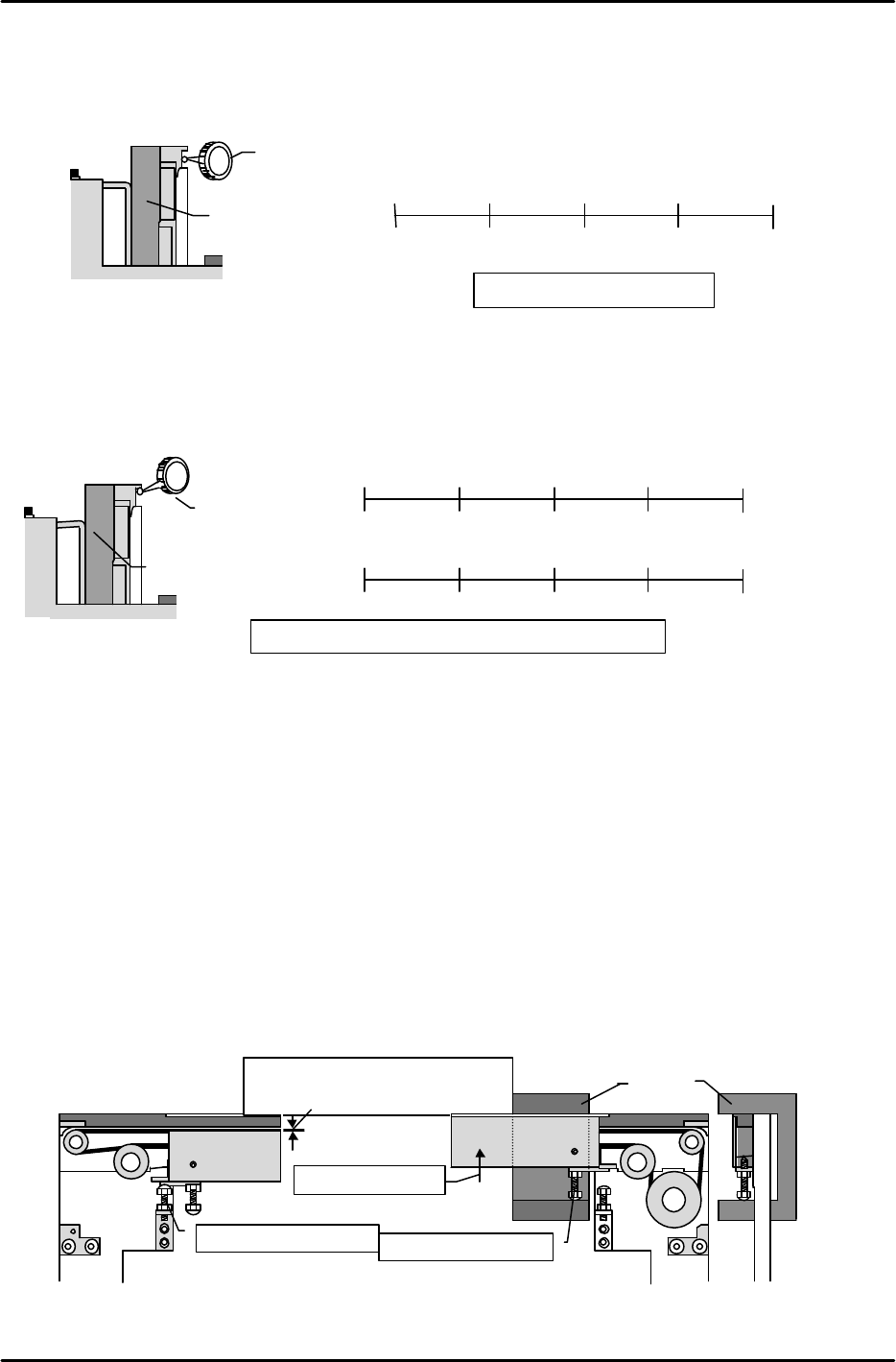
[3-6 ] Fixed Rail Parallelism and Flatness Measurement
1) Parallelism measurement
Measure the parallelism of the conveyor's fixed rail (side face) relative to the X-axis.
2) Flatness measurement
Adjust the secondary rail so that the width between conveyors is 200mm.
With the fixed rail as the zero point, measure (at bottom face of board clamp guide bar) the
difference between the fixed and secondary sides.
[3-7 ] Board Clamp Adjustment
1) DOWN limit adjustment
Verify that the table is at the DOWN position, then turn the DOWN limit adjusting bolt until
the clamper's top face is 0.3 to 0.5mm lower than the conveyor belt's top face.
2) UP limit adjustment
Loosen the UP limit adjusting bolt, then raise the clamper by hand until the adjusting jig is
pinned between the conveyor bracket's top face and the UP limit adjusting bolt (this height is
53.2 ^ 0.05). With the adjusting jig pinned in this manner, turn the UP limit adjusting bolt
until there is no jig looseness in the up/down directions, but not so tightly that the jig cannot
be extracted.
3) Post-adjustment check
* Use an I/O command to raise the table, verifying that the clamper operates smoothly.
* Lower the table and introduce a board into the system, verifying that the board passes
through the system in a smooth manner.
0.3 to 0.5mm distance between belt's
top face and clamper's top face
DOWN limit adjusting bolt
Raise the clamper
UP limit adjusting bolt
Jig
Machine viewed
from side
Dial gauge
Reference side conveyor
Machine viewed from right side
Tolerance: overall variation must be within 0.2mm
Reference rail
Moveable rail
0
112.5mm
255mm
337.5mm
(
)
(
)
( ) ( )
450mm
(
)
(
)
(
)
( )
( 0mm )
(
)
0
112.5mm
255mm
337.5mm
450mm
Dial gauge
Reference-rail
Machine viewed from
right side
Tolerance: 0.1 / 450mm
0
112.5mm
255mm
337.5mm
(
)
(
)
( ) ( 0mm )
450mm
(
)
FK-9F98-07 QP242E Training Text for Service Engineers
6th edition 3. QP242E Initial Adjustment (2) [7/12]
Fuji Machine Mfg. Co., Ltd. Okazaki
SMT Equipment Quality Assurance Dept.
Technical Support Div. Section No.2
3-7
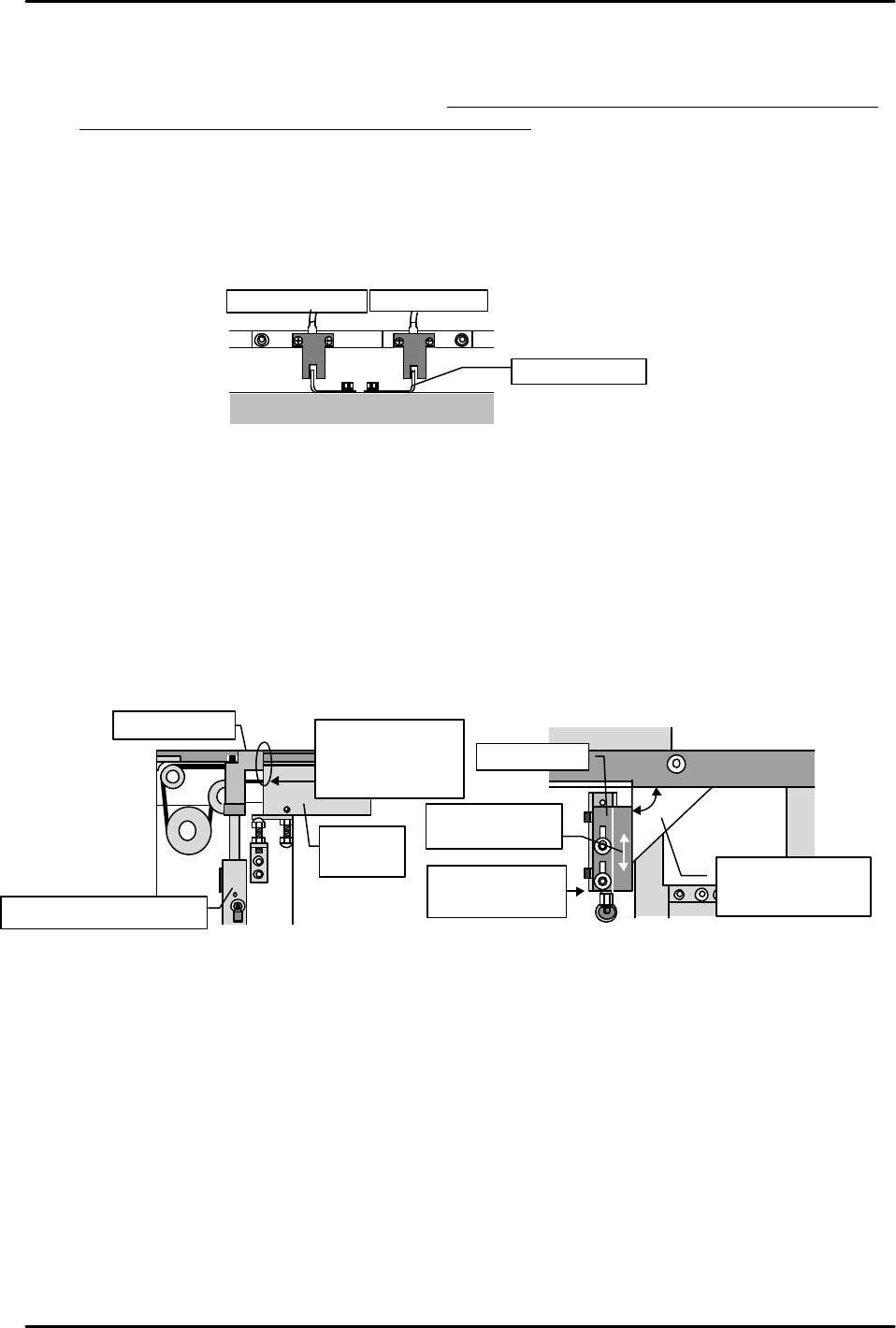
[3-8 ] Table UP Limit and DOWN Limit Sensor Adjustments
1) Turn the "Y023 CNVYR BRD CLMP" I/O command on to raise the table at the module in
question. Adjust the UP limit sensor dog so that the sensor switches on when a 4mm board
is clamped, and off when a 4.8mm board is clamped.
2) Turn the "Y024 CNVYR BRD UNCLMP" I/O command on to lower the table. Starting from
the position where the sensor is on, raise the dog until the sensor switches off. Next, lower
the dog to find the point where the sensor switches on again. Secure the dog 1mm below
that point.
3) Turn the I/O commands on and off to raise and lower the table, verifying that there is no
sensor hunting, etc.
[3-9 ] Board Stopper Sensor and Stopper Position Adjustments
1) Turn the "Y022 CVR BD STPR IN" I/O command off to lower the board stopper. Beginning
from the position where the DOWN limit sensor is on, gradually lower the sensor to find the
point where it switches off. Secure the sensor 1mm above this point.
2) Turn the "Y022 CVR BD STPR IN" I/O command on to raise the board stopper. Beginning
from the position where the UP limit sensor is on, gradually raise the sensor to find the
point where it switches off. Secure the sensor 1mm below this point.
3) Adjust the stopper position as shown below.
* Use the I/O command to raise the board stopper, and check the adjustments at the UP
limit position.
DOWN limit sensor UP limit sensor
Adjust dog
Table
Conveyor
Align cylinder
and bracket faces
Move bracket to
align faces
Use square jig to
verify 90 angle
(adjust if necessary)
Board stopper
Board stopper air cylinder
Board
clamper
Adjust the stopper
so that the stopper
and clamper faces
are evenly aligned
Board stopper
FK-9F98-07 QP242E Training Text for Service Engineers
6th edition 3. QP242E Initial Adjustment (2) [8/12]
Fuji Machine Mfg. Co., Ltd. Okazaki
SMT Equipment Quality Assurance Dept.
Technical Support Div. Section No.2
3-8
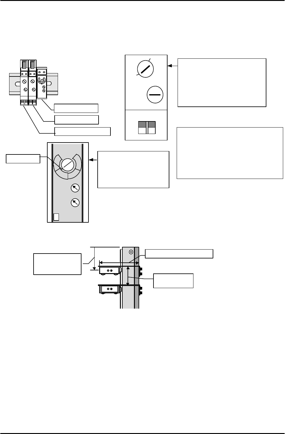
[3-10] Board Sensor Adjustment
1) Set the conveyor sensor amplifiers as shown below.
(At rear part-supply machines, the amplifiers are located on the right-side face of the MFU
mounting area. At front part-supply machines, the amplifiers are located in front of the
conveyor.)
2) Adjust the ICM deceleration and arrival sensor positions with reference to the following
illustration.
Yamatake Honeywell
DELAY
OMRON
Sensor switches
on 40mm from
conveyor end
40mm from
arrival sensor
67mm from conveyor end
Arrival sensor
Deceleration sensor
Pass sensor
Sensor amplifier
TIME
MAX
MIN D.ON
L.ON
1
2
3
4
LOW
HIGH
SENS
Red line
ON
Pass sensor
•DARAK ON
•TIME MIN
•SENS 3 Temporary
adjustment
SENS
L-ON
MODE
OFF-D
ON
OFF
D-ON
OFF-D
MIN MAX
Deceleration and arrival sensor
•LIGHT ON
•OFF-D OFF
•SENS Temporarily adjust to
activate for Fuji boards
•OFF-D volume
Set to maximum (full CW rotation)
Remarks
In cases where the board stopper pushes
boards which are being unloaded
upward, turn the arrival sensor's OFF-D
switch on and adjust the OFF-D volume.
If the OFF-D timer period is too long,
however, 2 consecutive boards will be
unloaded.