QP-242E 工程师培训手册 (6.0).pdf.pdf - 第9页
FK-9F98-07 QP242E Training Text for Service Engineers 6th edition Index [ 8 /8 ] Fuji Machine Mfg. Co., Ltd. Okazaki SMT Equipment Quality Assurance Dept. Technical Support Div. Section No.2 Index- 8 13.52 TZ-axis Interl…

FK-9F98-07 QP242E Training Text for Service Engineers
6th edition Index [7/8]
Fuji Machine Mfg. Co., Ltd. Okazaki
SMT Equipment Quality Assurance Dept.
Technical Support Div. Section No.2
Index-7
13.19 Provisional Proper Data Transmission 13-7
13.20 I/O Check of Each Type of Sensor and Solenoid 13-7
13.21 Prior to Zero Set Adjustment 13-8
13.22 Preliminary Zero Setting 13-8
13.23 TY-axis Zero Set Position Adjustment 13-8
13.24 Shuttle Assembly Y-direction Angle of Orientation Adjustment 13-9
13.25 Shuttle Jaw Front to Back Angle of Orientation Adjustment 13-9
13.26 Shuttle Jaw Parallel Adjustment 13-9
13.27 TZ-axis Zero Set Position Adjustment 13-10
13.28 Zero_Offset_TZ Measurement and Re-calibrating Zero Setting 13-10
13.29 Tray Holder Positioning Adjustment 13-11
13.30 Re-calibrating Zero Setting Prior to Proper Data Measurement 13-12
13.31 Remover_Position_X, Y, Z 13-12
13.32 Remover Lubrication 13-12
13.33 Prior to Connecting the MTU71E 13-12
13.34 MTU71E Connection 13-12
13.35 Tray Holder Levelness and Perpendicular Adjustment 13-13
13.36 Tray Eject Bracket Width & TZ-axis Perpendicular Check 13-14
13.37 TY Cam Clamp Bracket Adjustment 13-14
13.38 Tray Holder Lock Adjustment 13-14
13.39 Max, Min_Limit_Position 13-15
13.40 Original_Posiiton_TZ 13-15
13.41 Guide Rail Adjustment 13-15
13.42 TY-axis Interlock Sensor Adjustment 13-15
13.43 TY-axis Interlock Dog Adjustment 13-16
13.44 TZ-axis Interlock (Shuttle Forward Limit) Sensor Adjustment 1 13-16
13.45 Securing the MTU71E in Place 13-16
13.46 Shuttle Jaw Installation Position Adjustment and
Left to Right Angle Adjustment 13-17
13.47 Original_Posiiton_TY 13-17
13.48 TY-axis Retract Limit (Escape Position) Sensor Adjustment 13-18
13.49 Shuttle Jaw Opening Adjustment 13-18
13.50 Tray Pusher Installation 13-19
13.51 Tray Positioning Sensor Adjustment 13-19

FK-9F98-07 QP242E Training Text for Service Engineers
6th edition Index [8/8]
Fuji Machine Mfg. Co., Ltd. Okazaki
SMT Equipment Quality Assurance Dept.
Technical Support Div. Section No.2
Index-8
13.52 TZ-axis Interlock (Shuttle Forward Limit)
Sensor Adjustment 13-19
13.53 Operation Check of the Tray Check Sensors 13-19
13.54 Original_Position_Z1, Z2 Calibration 13-20
13.55 Original_Position_MTU7D?_X, Y Measurement 13-20
13.56 Reject Parts Conveyor Adjustment and Height Adjustment 13-21
13.57 MTU_Parts_Eject_Pos.CV_X, Y Measurement 13-22
13.58 Empty Tray Discard Box Existence Switch Check 13-22
13.59 Tray Pickup Check Sensor Settings 13-22
13.60 Reverse Transmission of Proper Data 13-24
14. Obtaining a Trace List with PC
14.1 Summary 14-1
14.2 Equipment 14-1
14.3 QP242E Setting 14-1
14.4 PC Setting 14-1
14.5 The procedure for obtaining trace lists 14-2
15. Digital Amplifier Parameter Chart
15.1 Digital Amplifier Parameter Chart 15-1
FK-9F98-07 QP242E Training Text for Service Engineers
6th edition 1. QP242E Initial Adjustment (1) [1/
6
]
Fuji Machine Mfg. Co., Ltd. Okazaki
SMT Equipment Quality Assurance Dept.
Technical Support Div. Section No.2
1-
1
[Chapter 1] QP242 Initial Adjustment (1)
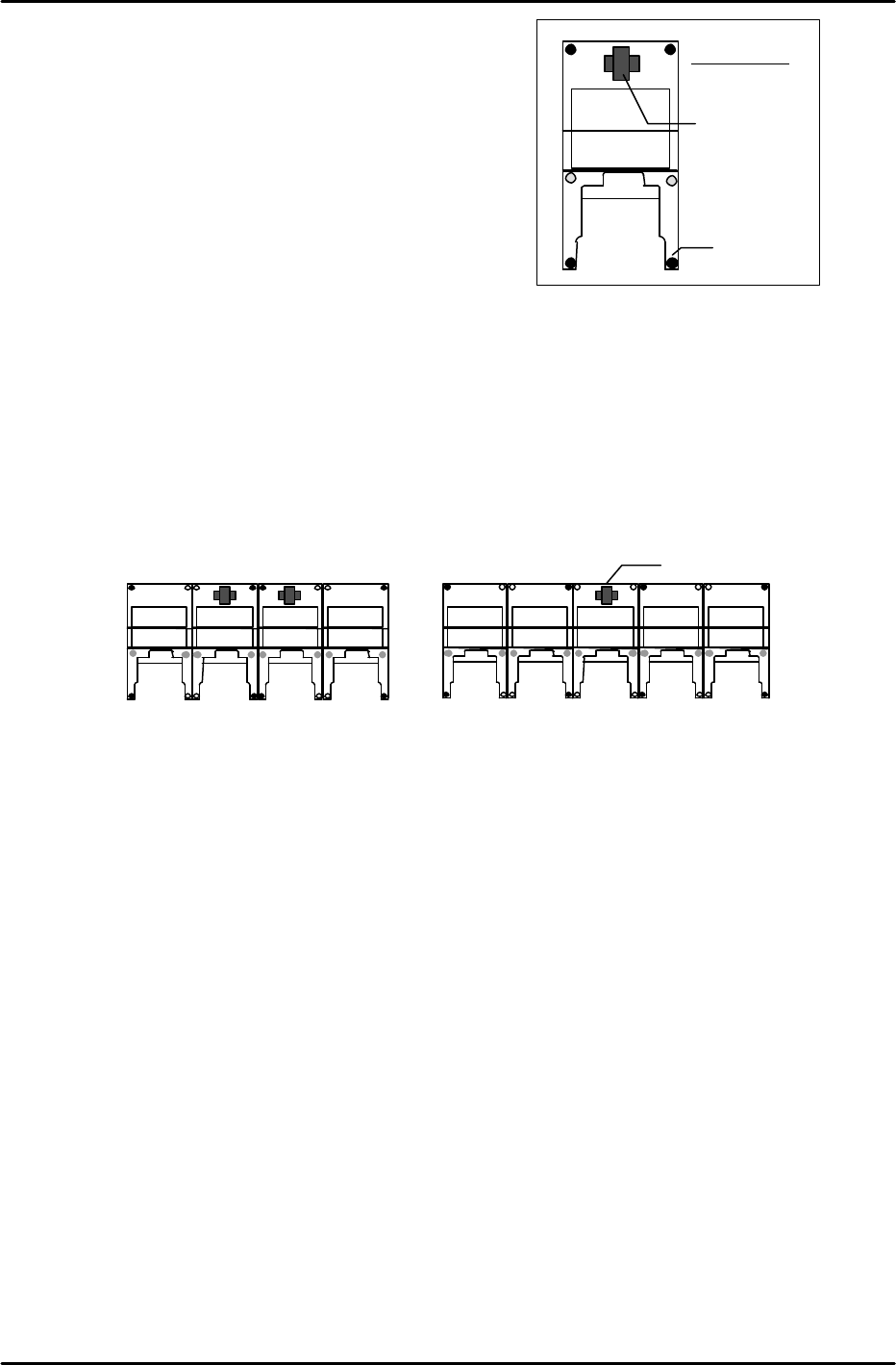
[1-1] Leveling the Machine
1) At systems with independent modules:
Place a level on the machine base and adjust the 6 leveling
bolts (black circles in figure at right) to level the
module in the front-back and right-left directions.
2) At systems with linked modules:
* When there are an even number of modules
(see figure below), place two levels on the two center
modules and turn the leveling bolts (shown as black circles in the figure below) to adjust the overall level.
After leveling the two center modules in this manner, verify that each of the modules is level. (The
further modules are from the center, the more likely they are to be out of level.
In such cases, further adjust the levels of the modules at both ends of the module row so that their levels
are the same, and are close to horizontal.)
* When there are an odd number of modules (see figure below), place a level on the center module and turn
the leveling bolts (shown as black circles in the figure below) to adjust the overall level. (The remaining
procedure is identical to that described above for an even number of modules.)
Leveling Device
(Level)
Leveling Bolt
Machine front
Leveling device (Level)
<Even number of modules>
Check
Check
<Odd number of modules>
Check
Check
Check
Check