QP-242E 工程师培训手册 (6.0).pdf.pdf - 第114页
FK-9F98-07 QP242E Training Text for Service Engineers 6th edition 13. MTU 71E Adjustment [ 12 /24] Fuji Machine Mfg. Co., Ltd. Okazaki SMT Equipment Quality Assurance Dept. Technical Support Div. Section No.2 13- 12 [1 3…
FK-9F98-07 QP242E Training Text for Service Engineers
6th edition 13. MTU 71E Adjustment [11/24]
Fuji Machine Mfg. Co., Ltd. Okazaki
SMT Equipment Quality Assurance Dept.
Technical Support Div. Section No.2
13-11
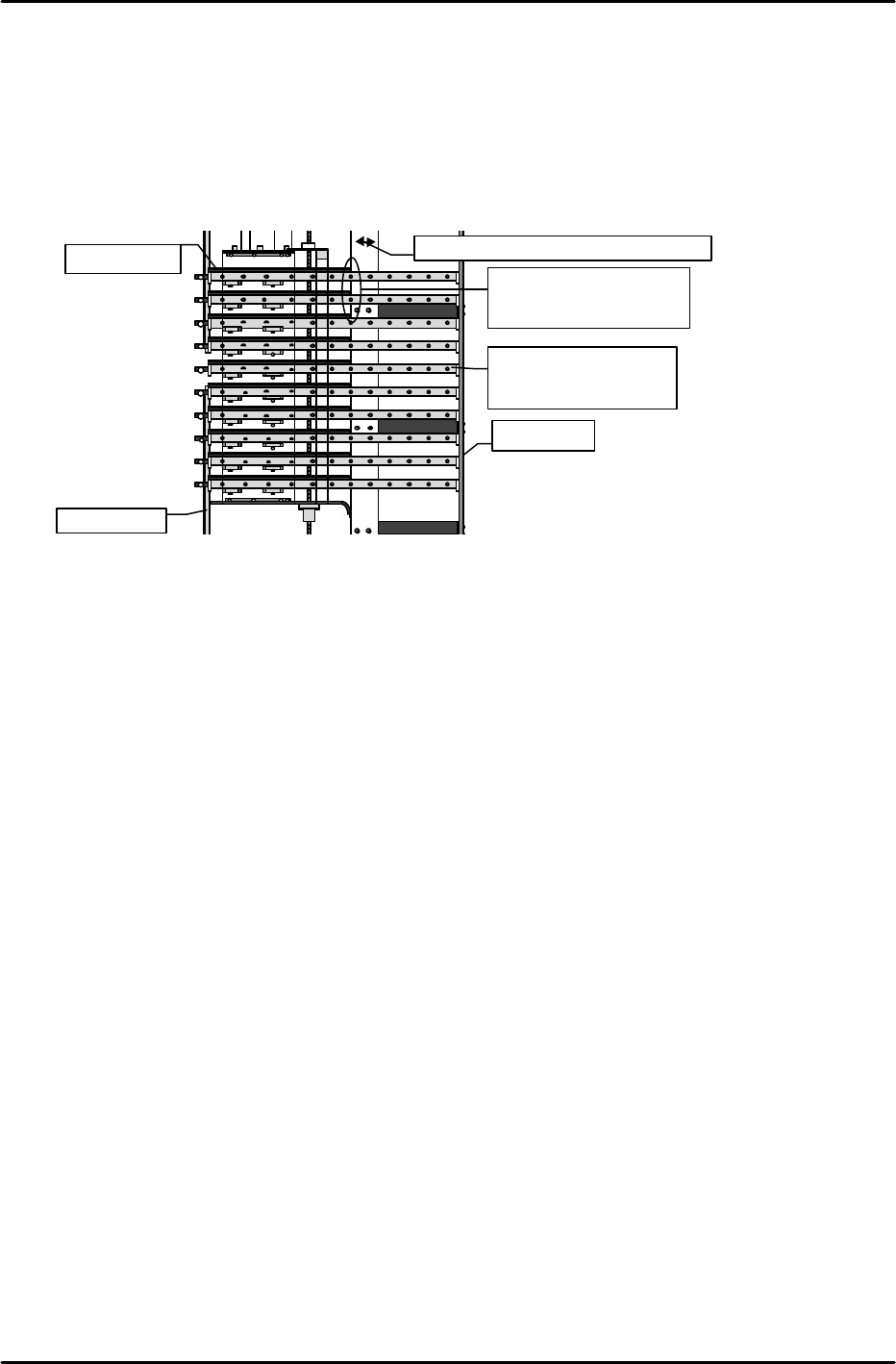
[13-29] Tray Holder Positioning Adjustment
1) When the tray holder pops out of the MTU, press the tray holder into the MTU by hand.
While checking that the tray holder does not interfere with any of the components such as
the rollers, move the fifth level tray holder to the center of the MTU by inching the TZ-axis.
2) Open the safety door and push all of the tray holders to the guide rail in the back of the unit.
Use a long scale on the portion of the tray holder that makes contact with the white plastic
guide attached to the door in order to verify which tray is entered the farthest back in the unit.
At this time verify that the deviation between all of the tray positions is not more than 1 mm.
3) Loosen the mounting bolts of the white plastic guide attached to the door.
4) Close the door and adjust the gap between the tray holder and guide that was verified
in step 2, within a range between 0.5 mm and 1 mm. Then secure the mounting bolts.
5) Move the TZ-axis up and down and verify that the gap between the tray holder and guide
lies within the range used in adjustment (0.5 mm ~ 1mm) at any position.
[13-30] Re-calibrating Zero Setting Prior to Proper Data Measurement.
[13-31] Remover_Position_X,Y,Z
1) Attach the measurement jig to the remover station, and then turn I/O Y000: REMOVER UP
on to raise the remover station.
2) Press EMERGENCY STOP and move the head placement hook mechanism by hand to the
station position.
3) Raise the Z-axis by hand and fine adjust the XY axes so that the pin on the placement hook
mechanism fits smoothly into the hole in the jig. This position becomes Remover_Position_X
and Y.
4) Lower the Z-axis from the Remover_Position_X and Y position to press the placement hook
pin into the jig hole. Lower the Z-axis further until the chuck-positioning pin is depressed 1
mm (spring return of 1mm). This position is the Remover_Position_Z value.
[13-32] Remover Lubrication
Apply grease (Daphne Eponex #2) to the placement hook mechanism pin and plate spring
such that the grease does not splatter.
Guide rail
Move the white plastic guide to adjust.
Tray holder
Guide rail
Move the fifth level
tray so that it comes to
the center of the MTU.
Adjust the gap between
the tray holder and the
plastic guide to 0.5 mm.
FK-9F98-07 QP242E Training Text for Service Engineers
6th edition 13. MTU 71E Adjustment [12/24]
Fuji Machine Mfg. Co., Ltd. Okazaki
SMT Equipment Quality Assurance Dept.
Technical Support Div. Section No.2
13-12
[13-33] Prior to Connecting the MTU71E
- Cable connections should be made with the power turned off.
- Connect the MTU7 unit to the machine in the zero set complete status with a magazine in the
standby status, with the TZ-axis moved to 0 pulses via inching and with the TY-axis in the
standby status at the forward limit.
- Once the unit is joined to the machine do not turn off the power until measurement of
Original_Position_TY is completed. If after the unit is connected to the machine the power
is cut and zero set is performed again there is a danger of damage resulting from contact
between the shuttle jaw and the tray holder.
Note: When MTU detachment is carried out over the course of installation or adjustment
work, always be sure that the TZ-axis position is lowered to 0 pulses beforehand using
magazine standby or the inching operation.
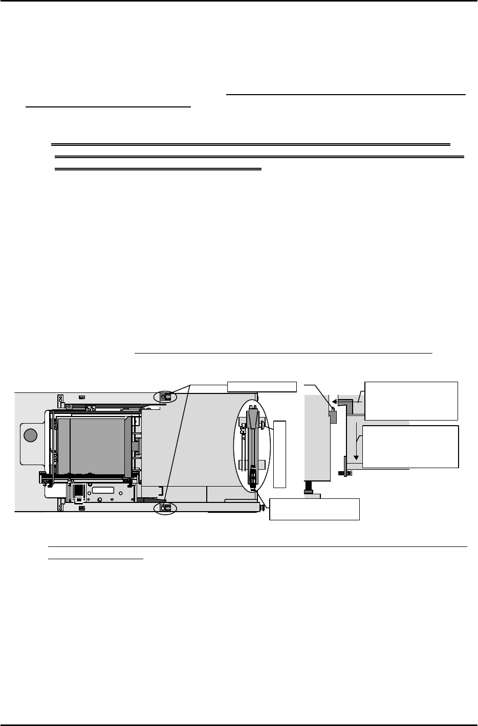
[13-34] MTU71E Connection
1) Use the hydraulic jack on the bottom of the safety door to raise the machine to a height at
which the lower surface of the positioning blocks on the inside of the MTU71E do not make
contact with the tips of the positioning pins on the machine.
2) Carefully move the MTU71E to the machine connection position checking that there is no
interference with the connecting cables or other parts of the unit and then align the
positioning blocks on the inside of the MTU71E with the positioning pins on the machine
side.
3) After this is completed, loosen the hydraulic jack valve to slowly lower the machine and
connect.
4) Verify that there is no gap between the top and bottom blocks and the contact surface and
check that the unit fits perfectly.
(Use a feeler gauge to confirm that the gap is within 0.03 mm.)
Note: If the bolt for adjusting the angle of orientation is loosened by mistake, adjustment must
be performed again.
MTU7
Loosen the air jack to
lower the machine
and connect the MTU
to the machine.
Loosen to lower
M/C
Leveling bolt
Raise the machine to
a height where there
is no interference
with the pins.
M/C
Positioning pins
Move the lever up
and down to raise.
Hydraulic jack
FK-9F98-07 QP242E Training Text for Service Engineers
6th edition 13. MTU 71E Adjustment [13/24]
Fuji Machine Mfg. Co., Ltd. Okazaki
SMT Equipment Quality Assurance Dept.
Technical Support Div. Section No.2
13-13
[13-35 ] Tray Holder Levelness and Perpendicularity Adjustment
With the tray holders in the set status, slide each tray holder plate in order towards the
machine. Use a dial gauge to provisionally measure the degree of levelness and
perpendicularity of the tray holder in relation to the machine base.
1) Levelness (1 ~ 9) Tolerance: All tray holders within +/- 0.8mm)
* If the degree of levelness is within the allowable tolerance
Level adjustment is unnecessary. Proceed to perpendicular measurement.
* If the front to back angle of orientation is raised in front
Loosen the angle adjustment bolt on the bottom of the unit to bring the front and back
measurement values within tolerance. (The front and back values should be adjusted as
close to zero as possible.) Furthermore, since the levelness of the tray holder extracted here
is taken into account, ignore the provisional level obtained in the previous process and
proceed with adjustment. The same also applies to the cases mentioned hereafter.
* If the left to right angle of orientation is not within the allowable tolerance range
Adjust the levelness until it is within the allowable tolerance by inserting spacers between
the ball screws on the left and right front side.
Once the levelness falls within the allowable tolerance range, proceed to the adjustment of
perpendicularity.
2) Perpendicularity (10 ~ 11) Tolerance: 0~ +/- 0.3 mm
* If perpendicular measurement is within tolerance
Perpendicular adjustment is unnecessary.
* If perpendicularity of all holders is tilted in the same direction and not within tolerance
Loosen the angle adjustment bolt on the bottom of the unit to free the unit. Loosen the
MTU71E position pin block lock bolts and fine adjust the installation position of the block so
that the perpendicularity falls within tolerance. After adjustment is completed, tighten the
angle adjustment bolt on the bottom of the unit again to adjust the level in the front to back
direction to the same value as adjusted in the previous process. Lastly check the
perpendicular measurement once again.
3) Carry out level and perpendicular measurement of the trays on all ten levels to verify that all
are within the allowable tolerances.
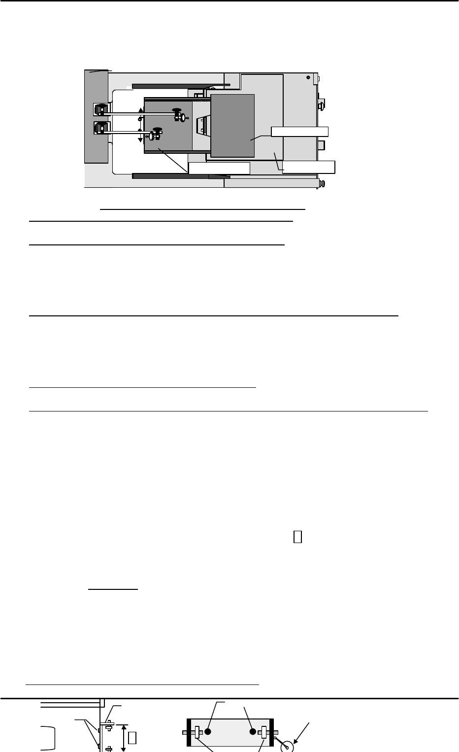
[13-36 ] Tray Eject Bracket Width & TZ-axis Perpendicularity Check
Verify that the width of the eject bracket (inside of bracket A) on all trays is 91.6mm (+/- 0.3
mm). If the width is not within this range then correct it. Next, set the dial gauge from the
machine on the bearing reference side, move the tray up and down and measure the
perpendicularity. Loosen the mounting bolts and adjust so that the perpendicularity of all
levels is within +/- 0.1 mm.
* Be careful that the bracket is not tilted at this time.
M/C
Base
①
④
⑦
②
⑤
⑧
③
⑥
⑨
Top of rack
Base plate
⑩
⑪
Tray holder
Use the machine end as a reference to measure perpendicularity.
A
Bearing reference side
Mounting bolts
Mounting bolts
Move the tray up and down and loosen the
mounting bolts to adjust so that all levels are
within +/- 0.1 mm of being perpendicular
.。