QP-242E 工程师培训手册 (6.0).pdf.pdf - 第22页
FK-9F98-07 QP242E Training Text for Service Engineers 6th edition 3. QP242E Initial Adjustment (2) [ 5 /12] Fuji Machine Mfg. Co., Ltd. Okazaki SMT Equipment Quality Assurance Dept. Technical Support Div. Section No.2 3-…
FK-9F98-07 QP242E Training Text for Service Engineers
6th edition 3. QP242E Initial Adjustment (2) [4/12]
Fuji Machine Mfg. Co., Ltd. Okazaki
SMT Equipment Quality Assurance Dept.
Technical Support Div. Section No.2
3-4
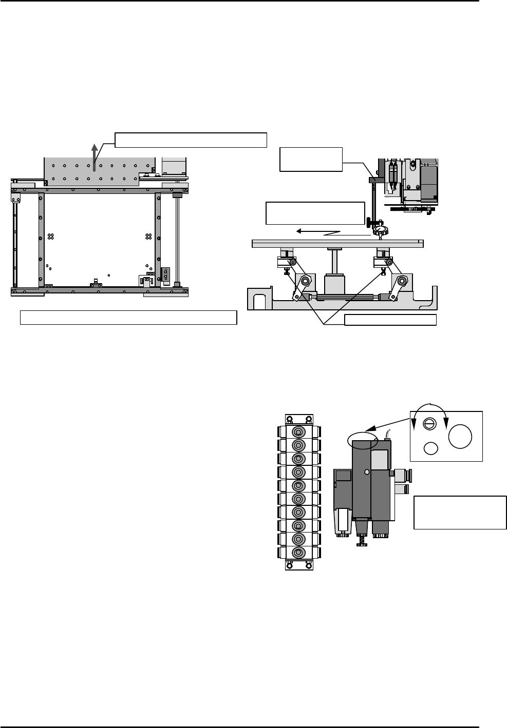
[3-3] Lifter Plate Height Measurement
1) Remove the backup plate from the rear of the machine (or from the front of the rear-loading
machines), and adjust the conveyor to its widest setting.
2) Using a jig, set a dial gauge on the X,Y robot. Use a calibrated techo type dial gauge.
3) Turn the "Y023 CNVYR BRD CLMP" I/O on to raise the table.
4) Measure the heights of the table's 4 corners and verify that the dial gauge reading is "0".
If the reading is other than "0", use the adjusting bolts to adjust the height.
5) After verifying the dial gauge reading, take measurements at 9 points on the table.
[3-4] Air Valve Throttle Adjustment
Open the machine's rear door and set the valves (located on the sides of the left and right supports) as
shown below.
Ø Lifter cylinder boa (old)
Valves at right-side support (from top) Number of turns (from full close)
1) Board stopper up 2 turns
2) Board stopper down 2 turns
3) Conveyor board clamp low-speed 0.5 turns
4) Conveyor board unclamp low-speed 0.75 turns
5) Conveyor board unclamp high-speed 0.75 turns
6) Conveyor board clamp high-speed 4.25 turns
7) Nozzle shutter close (for single nozzle) 2 turns
8) Nozzle shutter open (for single nozzle) 2 turns
9) Nozzle changer up (for single nozzle) 1.25 turns
10) Nozzle changer down (for single nozzle) 2 turns
Valves at left-side support
11) Board vacuum (vacuum break) 1 turn
12) Discharge time adjusting throttle
(6 turns from full open)
Ø Lifter Cylinder Boa (new)
Valves at right side support Numbers of turns(from fully closed position)
3) Conveyor board clamp low-speed 0.75 turns
4) Conveyor board unclamp low-speed 1 turn
5) Conveyor board unclamp high-speed 1.25 turns
6) Conveyor board clamp high-speed 5 turns
Settings for other valves are the same for lifter cylinder boa up (front) .
1 2 3
4 5 6
7 8 9
1
( )
2 ( )
3 ( )
4 ( )
5 ( )
6 ( )
7 ( 0mm )
8 ( )
9 ( )
Measure with table raised
Tolerance: Overall variation should be within 0.1mm
Remove the backup plate
Table
Measure table surface
using the dial gauge
Height adjusting bolts
Jig for setting
dial gauge
⑪
12)
1)
2)
3)
4)
5)
6)
7)
8)
9)
10)
Faster Slower
Discharge time
adjusting throttle
CW rotation: slower
CCW rotation: faster
FK-9F98-07 QP242E Training Text for Service Engineers
6th edition 3. QP242E Initial Adjustment (2) [5/12]
Fuji Machine Mfg. Co., Ltd. Okazaki
SMT Equipment Quality Assurance Dept.
Technical Support Div. Section No.2
3-5
•How to distinguish lifter cylinder boa up front & rear.
Boa up (front) = Cylinder side and joint side arm width the same (10mm).
Boa up (rear) = Cylinder side is 18mm longer than the joint side.
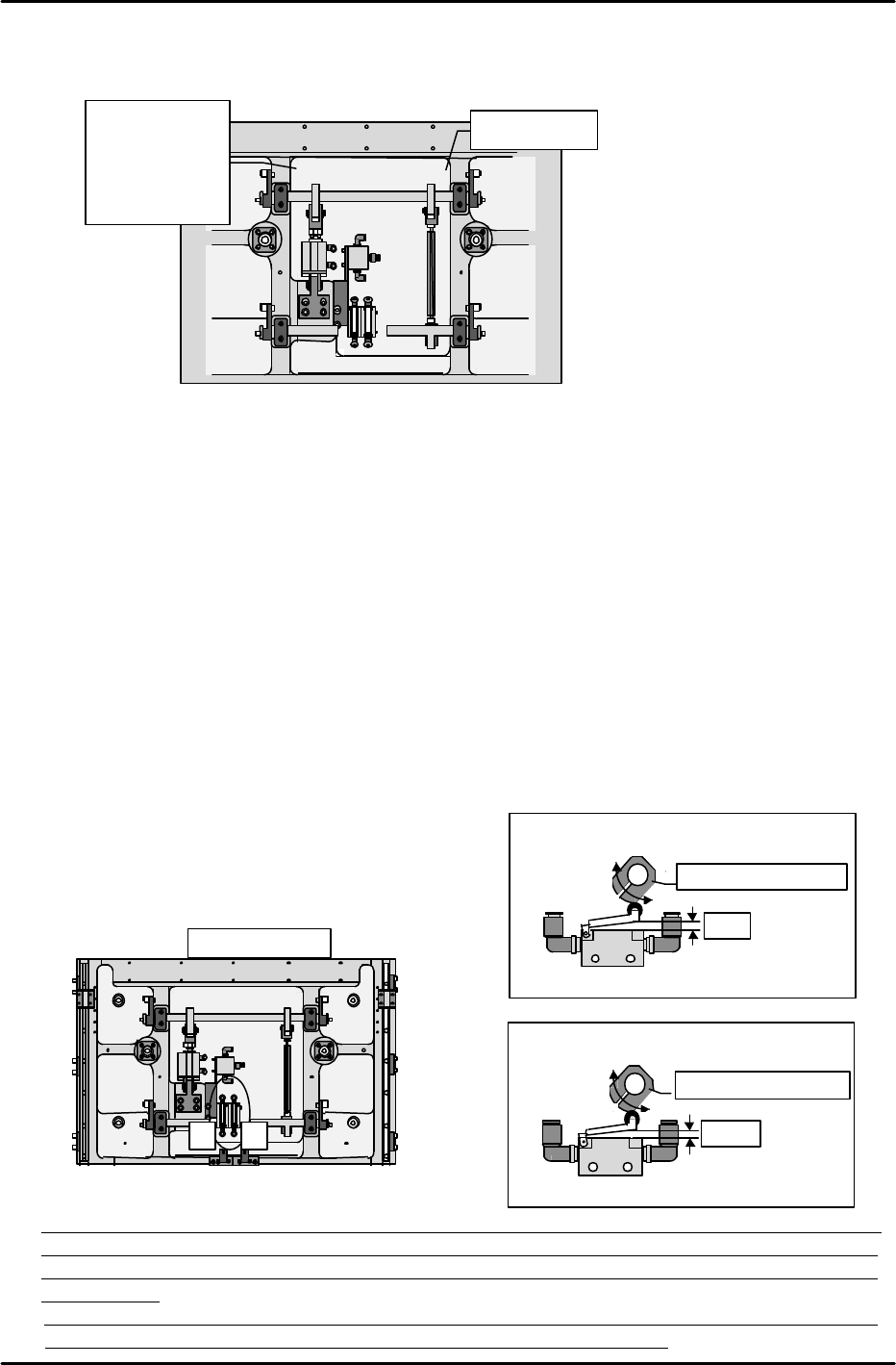
[3-5 ] Table Mechanical Valve Adjustments
Note: The following adjustment should be performed only after the lifter plate height
measurement is completed.
1) High-speed cam adjustment for DOWN motion
1. Lower the lifter plate to a point 7mm below the UP limit.
2. Insert a 3mm spacer beneath the lever which presses the mechanical valve switch, then
press the lever against this spacer and secure the cam, making sure that the cam is
against the lever.
2) High-speed cam adjustment for UP motion
1. Position the lifter plate at its DOWN limit position.
2. Insert a 2.5mm spacer beneath the lever which presses the mechanical valve switch, then
press the lever against this spacer and secure the cam, making sure that the cam is
against the lever. (The lifter plate is probably at its DOWN limit at this time, leaving no
space to insert your hand in order to secure the cam. Therefore, make a mark to show
the cam and shaft positional relationship, then raise the lifter plate to its UP limit
position and secure the cam at the marked position. Because the PCB is subjected to
impacts each time this cam adjustment procedure is performed, be sure to perform it
correctly
the first time.)
Table mechanical valve adjustment
Turn the cam to adjust as shown below.
(Be sure to note the cam
direction)
* Note: Although the loading cycle time measurement procedure is described in section [9-1], the
air valve and mechanical valve adjustments performed as described in sections [4-4] and [4-5]
should be readjusted so that they are as close as possible to the reference cycle time values
shown below.
Reference cycle time values: Loading time (4.11 sec) = unclamping time (0.64 sec) + board
unloading and board loading time (2.26 sec) + clamping time (1.21 sec)
1 2
Machine rear
Table bottom
(1) High-speed cam for board DOWN limit
Adjust (turn) to 3mm
3mm
Lifter plate positioned at 7mm below the UP limit
(2) High-speed cam for board UP
Adjust (turn) to 2.5mm
2.5mm
Lifter plate positioned at
DOWN limit0
Width 10mm
•
Boa up
front
à width 10mm
•Boa up rear
à width 18mm
FK-9F98-07 QP242E Training Text for Service Engineers
6th edition 3. QP242E Initial Adjustment (2) [6/12]
Fuji Machine Mfg. Co., Ltd. Okazaki
SMT Equipment Quality Assurance Dept.
Technical Support Div. Section No.2
3-6
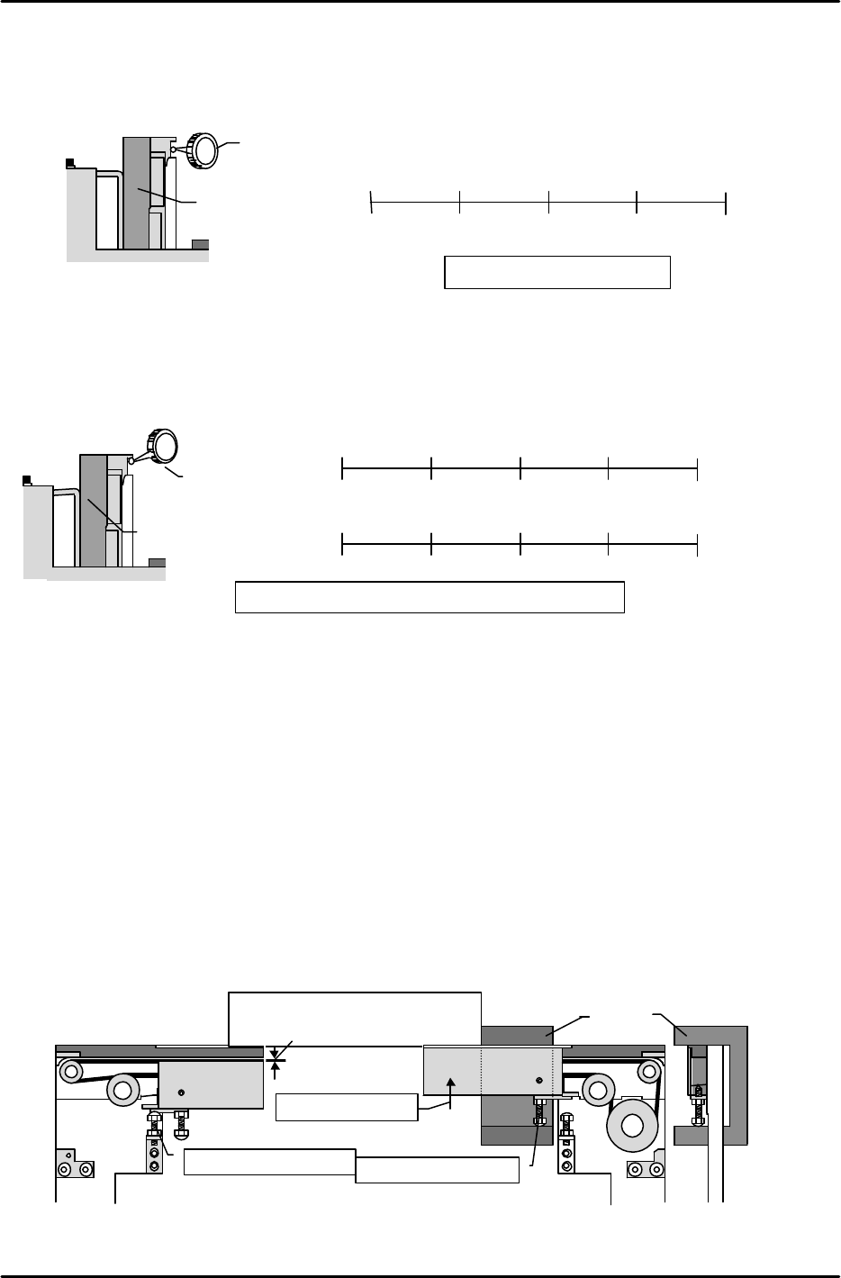
[3-6 ] Fixed Rail Parallelism and Flatness Measurement
1) Parallelism measurement
Measure the parallelism of the conveyor's fixed rail (side face) relative to the X-axis.
2) Flatness measurement
Adjust the secondary rail so that the width between conveyors is 200mm.
With the fixed rail as the zero point, measure (at bottom face of board clamp guide bar) the
difference between the fixed and secondary sides.
[3-7 ] Board Clamp Adjustment
1) DOWN limit adjustment
Verify that the table is at the DOWN position, then turn the DOWN limit adjusting bolt until
the clamper's top face is 0.3 to 0.5mm lower than the conveyor belt's top face.
2) UP limit adjustment
Loosen the UP limit adjusting bolt, then raise the clamper by hand until the adjusting jig is
pinned between the conveyor bracket's top face and the UP limit adjusting bolt (this height is
53.2 ^ 0.05). With the adjusting jig pinned in this manner, turn the UP limit adjusting bolt
until there is no jig looseness in the up/down directions, but not so tightly that the jig cannot
be extracted.
3) Post-adjustment check
* Use an I/O command to raise the table, verifying that the clamper operates smoothly.
* Lower the table and introduce a board into the system, verifying that the board passes
through the system in a smooth manner.
0.3 to 0.5mm distance between belt's
top face and clamper's top face
DOWN limit adjusting bolt
Raise the clamper
UP limit adjusting bolt
Jig
Machine viewed
from side
Dial gauge
Reference side conveyor
Machine viewed from right side
Tolerance: overall variation must be within 0.2mm
Reference rail
Moveable rail
0
112.5mm
255mm
337.5mm
(
)
(
)
( ) ( )
450mm
(
)
(
)
(
)
( )
( 0mm )
(
)
0
112.5mm
255mm
337.5mm
450mm
Dial gauge
Reference-rail
Machine viewed from
right side
Tolerance: 0.1 / 450mm
0
112.5mm
255mm
337.5mm
(
)
(
)
( ) ( 0mm )
450mm
(
)