QP-242E 工程师培训手册 (6.0).pdf.pdf - 第36页
FK-9F98-07 QP242E Training Text for Service Engineers 6th edition 5. Before Beginning the Proper Data Measurements [ 1 / 6 ] Fuji Machine Mfg. Co., Ltd. Okazaki SMT Equipment Quality Assurance Dept. Technical Support Div…

FK-9F98-07 QP242E Training Text for Service Engineers
6th edition 4. Axis Zero Setting Adjustment [6/6]
Fuji Machine Mfg. Co., Ltd. Okazaki
SMT Equipment Quality Assurance Dept.
Technical Support Div. Section No.2
4-6
Axis Zero Setting Adjustments in the Mechanical Check Mode
[4-11]
Before Beginning the Axis Zero Setting Adjustments
1) Start up the machine in the "Mechanical Check" mode.
2) If the coupling and belt are removed with the 200V power on,
the motor will vibrate. To prevent this, press the Emergency
Stop button (200V off), then connect a digital operator to
ch3 of each axis amplifier and lower the CN-04 gain to " 80" .
[4-12]
X-Axis Zero Setting Adjustment and Belt Tension Adjustment
1) Remove the X-axis timing belt.
2) Use the following command sequence to select module 1: [MODULE FIX]è[Number of
module to be adjusted (Ex.)]è [CR]. Next, execute a return using the [RETURN] command.
Continue by selecting the X-axis as follows: [MOVE]è[ZERO SETUP]è[NEXT AXIS].
Press [START] to begin the zero setting operation.
3) Block the X-axis deceleration sensor beam and end the zero setting operation.
4) Execute the [RETURN] è [STROKE] è [NEXT AXIS] commands to select the X-axis, then
move (by inching) the X-axis to the 4000 pulse position (-4000 at rear part-supply machines)
while watching the displayed counter reading.
5) Move the head to the mechanical stopper at the machine's right side (as viewed from the part
supply side), then attach the timing belt and adjust its tension.
Belt tension tolerance : 227HZ ± 10HZ
After adjusting the belt tension, move the head back to right-side mechanical stopper position
and verify that the counter reading is within 4000 ± 200 pulses (-4000 pulse position at rear
part-supply machines).
* Flip chip modules have a coupling drive system rather than a belt drive. At these
modules, adjust the X-axis to a 4000 ± 100 pulse position
6) After completing the above adjustment, adjust the X-axis deceleration sensor position so that
the sensor switches on at the -5500 pulse position. Following this adjustment, use the
"CHECK, X006, X AXIS ZERO" I/O to verify that the sensor switches on at the -5500 ± 100
pulse position (5500 pulse position at rear part-supply machines).
7) After the adjustment, connect a digital operator to CN-04 again and return the gain to "500"
from "80".
[4-13] Y-Axis Zero Setting Adjustment
1) Perform the Y-axis zero setting adjustment in the same manner as that described for the X-
axis, adjusting until the values shown in section [4- 6] are obtained.
2) After the adjustment, connect a digital operator to CN-04 again and return the gain to "500"
from "80".
[4-14] Z-Axis Zero Setting Adjustment and Belt Tension Adjustment
1) Perform the Z-axis zero setting adjustment in the same manner as that described for the X-
axis, adjusting until the values shown in section [4- 7] are obtained.
2) After the adjustment, connect a digital operator to CN-04 again and return the gain to "450"
from "80".
[4-15 ] Q-Axis Zero Setting Adjustment
1) Perform the Q-axis zero setting adjustment in the same manner as that described for the X-
axis, adjusting until the values shown in section [4 - 8] are obtained.
2) After the adjustment, connect a digital operator to CN-04 again and return the gain to "300"
from "80".
SAV1
SAV2
SAV3
SAV4
X
Y
Q
Z
FK-9F98-07 QP242E Training Text for Service Engineers
6th edition 5. Before Beginning the Proper Data Measurements [1/6]
Fuji Machine Mfg. Co., Ltd. Okazaki
SMT Equipment Quality Assurance Dept.
Technical Support Div. Section No.2
5-1
[Chapter 5] Before Beginning the Proper Data
Measurements
[5-1] Attaching the Nozzle Changer Holder Bracket and Q-Cover (For Index Types Only)
1) End the Z-axis zero setting operation and lock the servo.
2) Mount the holder bracket at the head from which it was removed (see section [5-4]), partially
tightening it there with the M5 x 10 bolts and disc springs.
3) Use the M3 x 5 bolts and spring washers to mount the Q-cover for the index nozzle at the bottom of
the placing head.
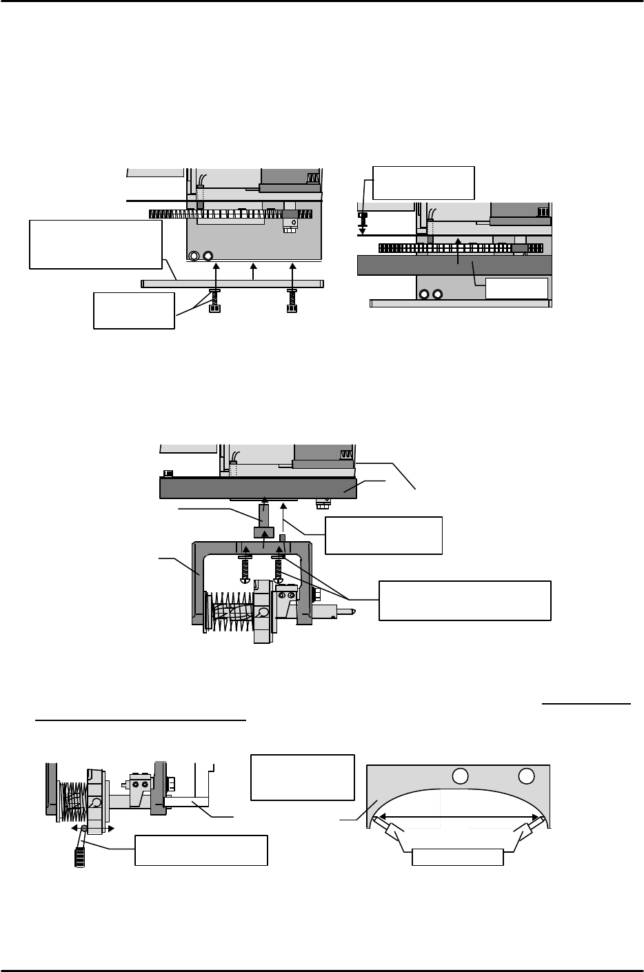
[5-2] Mounting the Index Holder and Adjusting the Holder Bracket
1) Mount Index type holders on the gear in the same manner as the Q-axis zero measurement jig,
using the M5 x 15mm machine screws and spring washers. When mounting the holder, note the
positioning pin on the top face. A stepped collar (28mm thick) is installed between the holder and
the gear.
2) With the holder shaft against the bracket, turn the holder to the shaft's most contracted position.
At this position, set a dial gauge in the Y-direction and adjust until the holder's inner gap is
within a "0 to 0.05mm" range, with the holder shaft ends making contact with the bracket's
left and right sides in an even manner.
Holder shaft
Even contact at
right and left
Dial gauge reading
within 0.01 to 0.05mm
Nozzle changer
holder bracket
Collar
Align pin hole and
mount on the gear
Index holder
M5 x 15mm machine screws
and spring washers for holder
Q-cover
M5 x 10 / disc
springs
Nozzle changer
holder bracket
(partially secured)
M3 x 5 /
spring washers
Q-cover
FK-9F98-07 QP242E Training Text for Service Engineers
6th edition 5. Before Beginning the Proper Data Measurements [2/6]
Fuji Machine Mfg. Co., Ltd. Okazaki
SMT Equipment Quality Assurance Dept.
Technical Support Div. Section No.2
5-2
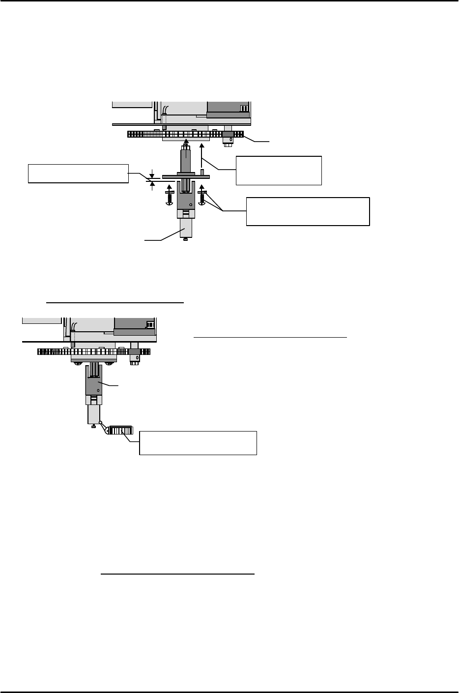
[5-3] Mounting Shafts For Single Nozzles
* Note that the inner spring used in systems with placing pressure control is different from the
standard item.
1) Verify that there is a 2mm gap between collars. If the gap is other than 2mm, request
instructions from the supervisor.
2) In the same manner as for index holders, mount the single holder in the prescribed direction (note
positioning pin) using the M5 x 12mm machine screws and spring washers.
[5-4] Measuring the Single Shaft Swing
Set a dial gauge at the bottom of the single shaft and measure the shaft swing.
(This measurement is not required for index nozzles.)
Tolerance: 0.1 / 360degrees
[5-5] Adjusting the Pressure Control Sensor
1) Mount a standard nozzle on the head.
2) Clamp a standard PCB on the main conveyor.
3) Move the nozzle to the PCB surface and lower the Z-axis to the position specified by the Z0 Proper
data value.
4) Loosen the hollow bolt which secures the sensor and adjust the sensor position so that there is a
0.3mm gap between the shaft collar's side face and the sensor's side face.
5) Adjust the bracket position up and down until the pressure control sensor switches on when the
Z-axis is lowered 0.15 ± 0.015mm (100 ± 10 Pls) from Z0.
Align pin hole and
mount gear
M5 x 12mm machine screws
and spring washers
Gear
Single nozzle shaft
Verify that gap is 2mm
Single nozzle shaft
Set dial gauge at bottom of
shaft and measure swing
Max. swing amount: mm