QP-242E 工程师培训手册 (6.0).pdf.pdf - 第108页
FK-9F98-07 QP242E Training Text for Service Engineers 6th edition 13. MTU 71E Adjustment [ 6 /24] Fuji Machine Mfg. Co., Ltd. Okazaki SMT Equipment Quality Assurance Dept. Technical Support Div. Section No.2 13- 6 [1 3- …
FK-9F98-07 QP242E Training Text for Service Engineers
6th edition 13. MTU 71E Adjustment [5/24]
Fuji Machine Mfg. Co., Ltd. Okazaki
SMT Equipment Quality Assurance Dept.
Technical Support Div. Section No.2
13-5
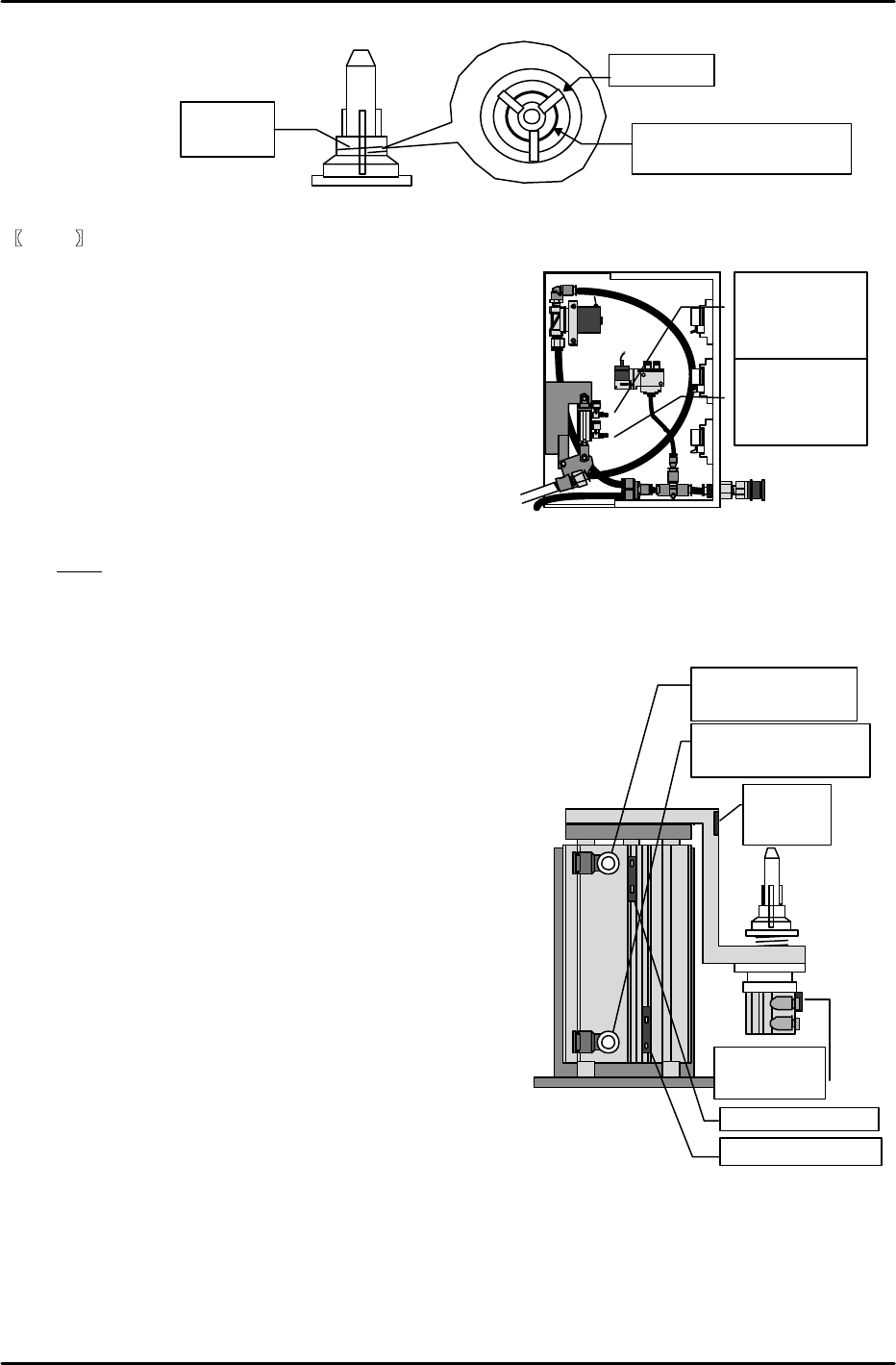
Station lowered (open 4
turns from the fully
closed status)
Station raised (open 4
turns from the fully
closed status)
View from the side of
the remover station
Lower limit sensor
Upper limit sensor
Chuck
operation
check sensor
Remover
detection
sensor
【
13-13
】
Speed Controller Adjustments for the Remover
1) Remover station up/down
Adjust the speed controller for the remover station
up/down cylinder open four turns from the fully
closed status.
2) Remover air hose up/down
Adjust the air hose up/down cylinder speed controller
in the remover relay box open one turn from the fully
closed status.
3) After both speed controllers are adjusted use
I/O Y000: REMOVER UP
and Y001: REMOVER DWN
to check the up/down operation of the remover
station.
Note: The speed controllers use a meter-out system.
[13-14] Remover Station Sensor Adjustment
1) Remover station up/down check sensors
Turn I/O Y000: REMOVER UP on to raise the remover station. First, slide the sensor up from the
upper limit sensor on position toward the upper end where the
sensor goes off. Then gradually lower the sensor to find the exact
position at which the sensor comes on.
From this position lower the sensor another 1 mm and secure the
sensor in place in that position.
Follow the same procedure for the lower limit sensor.
Lower the sensor toward the end where the sensor goes off
and then gradually raise it to the position at which the
sensor comes on. Raise the sensor another 1 mm from
this position and secure it in place.
2) Remover chuck open/close check sensor
Turn I/O Y005: RMVR UNCHUCK on (jaw closed),
insert the remover in the chuck positioning pin and then
go to the I/O again and return Y005: RMVR UNCHUCK
to the off status (jaw open) for operation.
At this time the chuck jaw should be aligned along the
vertical groove in the remover and should fit securely in
the ring-shaped groove in the rear. Adjust so that the
cylinder upper limit sensor responds at the same time
as this status is achieved.
On the other hand, also verify that the upper limit
sensor does not come on if the jaw is not aligned with either of these
grooves.
3) Remover detection sensor
Adjust the sensor volume so that the sensor is on when the remover is in operation and off when
the remove is not present. Verify that there is no change in the response even if the remover
deviates in the rotation direction by the amount of slack that exists during the chucking operation.
(As a criterion the volume of the sensor located on the side of the chuck positioning pin mounting
bracket should be set to the highest value.) Verify that the detection status remains stable even if
there is only slight clamping pressure during the remover operation.
Springs should intersect
between the claws of the jaw.
Ring
spring
Top view
Chuck claw
Inside the remover relay box
Air hose raised
(Open one turn
from fully closed
status)
Air hose lowered
(Open one turn
from fully closed
position)
FK-9F98-07 QP242E Training Text for Service Engineers
6th edition 13. MTU 71E Adjustment [6/24]
Fuji Machine Mfg. Co., Ltd. Okazaki
SMT Equipment Quality Assurance Dept.
Technical Support Div. Section No.2
13-6
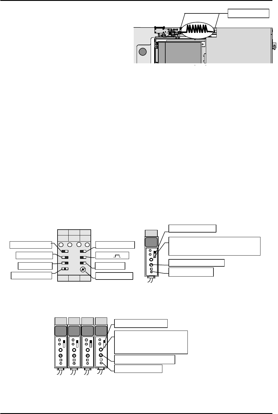
[13-15] Securing the Remover Station Air Hose
Align the air hose in the direction shown in
the figure and then secure in place.
Check that the remover does not stretch the
hose even as it moves up and down.
Also do not forget to apply LOCTITE 222 to
the air hose joints.
[13-16] Remover Operation Check
1) Set I/O Y02B: REMOVER VACUUM on and pickup a 240 g empty tray (maximum
allowable weight) with the remover to verify that it holds the tray with no problem.
Also measure the placement pressure.
2) Remover tubing mechanism operation check
* When the remover head is operating at the station
I/O OUT Y000 REMOVER UP
This I/O comes on and the remover station and remover tubing interlock and ascend.
I/O OUT Y001 REMOVER DWN
This I/O comes on and the remover station and remover tubing interlock and descend.
* When the remover head is not operating at the station
I/O OUT Y000 REMOVER UP
This I/O comes on and with the remover tubing raised, the remover station alone ascends.
I/O OUT Y001 REMOVER DWN
This I/O comes on and with the remover tubing raised, the remover station descends.
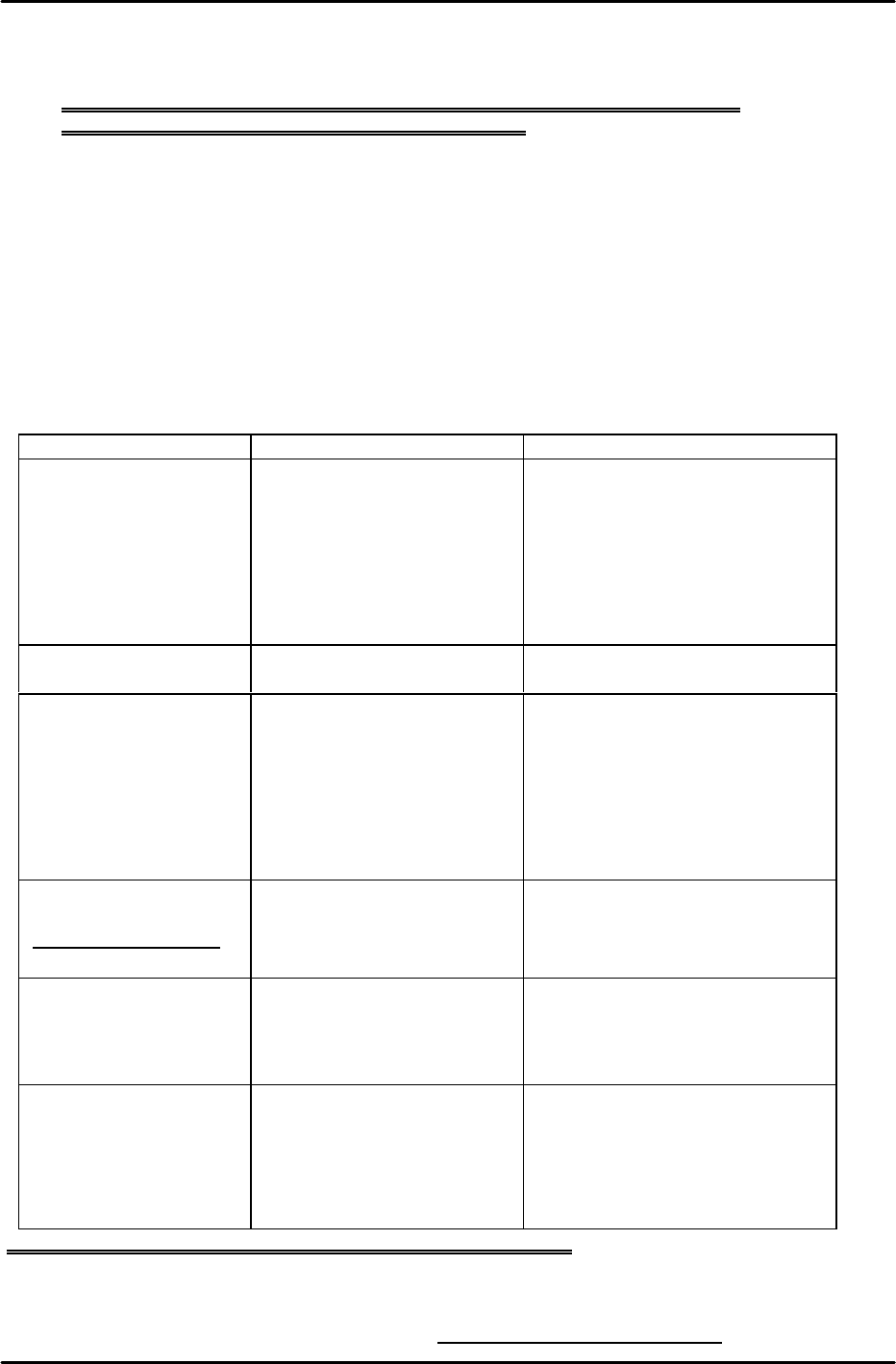
[13-17] Empty Tray Eject Detection Sensor & Tray Holder Load Check Sensor Amp Settings
1) Set the empty tray eject detection sensor amp that is located on the same side of the tray as the
built-in TZ-axis motor, as shown in the figure on the left.
2) Adjust the sensor mounting bracket height so that the tray eject detection sensor responds at a
position 3 mm higher than the top of the empty tray discard box.
3) Set the amp of the internal TZ-axis interlock sensor located on the right side of the tray as shown
in the figure on the right.
[13-18] Tray Positioning and Tray Addition Sensor Amp Settings
Set the four amps installed on the outer side of the TY-axis frame as shown in the figure below.
KEYENCE
OFF
ALM
OUT
SENS.
TIME.
MODE
0.04
5
5
KEYENCE
OFF
ALM
OUT
SENS.
TIME.
MODE
0.04
5
5
KEYENCE
OFF
ALM
OUT
SENS.
TIME.
MODE
0.04
5
5
KEYENCE
OFF
ALM
OUT
SENS.
TIME.
MODE
0.04
5
5
Set MODE to "5".
Set the timer to "0.04".
Set to “ALM.OFF”.
Trip the sensor OFF then turn it
in reverse and set it two
markings beyond the mark at
which it comes ON.
Set to
“NORM”
.
Set to
“OR”
.
Set to
“1S”
.
Set to
“NORM”
.
Set to
“
“
.
Set to
“ON-D”
.
Set to
“ON”
.
Set to
“MIN”
.
Empty tray eject detection sensor
KEYENCE
OFF
ALM
OUT
SENS.
TIME.
MODE
0.04 5
5
Set MODE to "1".
Set the timer to "0.04".
Trip the sensor OFF then turn it in
reverse and set it two markings beyond
the mark at which it comes ON.
Set to "ALM.OFF".
Tray holder load check sensor
M/C
リムー
リムー
MTU
Apply Loctite222
FK-9F98-07 QP242E Training Text for Service Engineers
6th edition 13. MTU 71E Adjustment [7/24]
Fuji Machine Mfg. Co., Ltd. Okazaki
SMT Equipment Quality Assurance Dept.
Technical Support Div. Section No.2
13-7
[13-19] Provisional Proper Data Transmission
1) Reconfirm that all connection cables are in fact connected to the machine and then turn the
power on.
Note: If the remover station lower limit is not ON, the machine will return a
communications error and will not properly boot up.
2) Open the QP242 Proper data from F4G, set the items required for the MTU71, and verify.
(Example) Set PLM? (number of module to which MTU71 is joined) _Device_Type to "3"
(MTU71).
Enter a suitable value in Original Position TY. (Set a value that does not
exceed Max Limit Position TY.)
Set PLM?_Pickup_remover_Org_X to "-56" and set Pickup_remover_Org_Y to "63".
3) Transmit the Proper data to the machine. Once transmission is successfully completed cut
the power to the machine and then reboot.
[13-20] I/O Check of Each Type of Sensor and Solenoid
Go to the I/O command on the machine and confirm that the following input and output
signals are working correctly.
Input Output
Remover station vicinity X002: RMVR EXIST CHK
X003: RMVR CHUCKING
X00A: REMOVER UP END
X00C: REMOVER DN END
Y005: RMVR UNCHUCK
Y000: REMOVER UP
Y001: REMOVER DWN
Empty tray removal X016: TRAY REMOVE CK Y02B: REMOVER VACUUM
Each interlock sensor X017: TRAY STORE CHK
X01D: TZ MV OK POS2
X03E: TZ MV OK POS1
X03F: TY MOVE OK POS
Tray part pickup position
(Refer to note below.)
X038: CHK(TZ,POS1,2)
X039: CHK(TY,ADD1,2)
Y028: TRAY 1/2 SEL
Y029: REACH/TRAY SEL
NG Parts Conveyor X018: NG PARTS FULL
X019: PARTS CV COUNT Y027: PARTS CONV ON
Other X03C: TZ SPD DWN PNT
X03D: TY SPD DWN PNT
X028: TRAY ORG SW Y02A: TRY ORG LAMP
Remarks: When odd numbered device (1, 3, 5~) input is checked Y028: TRAY 1/2 SEL X
Y029: REACH/TRAY SEL O
When even numbered device (2, 4, 6~) input is checked Y028: TRAY 1/2 SEL O
Y029: REACH/TRAY SEL O
Note: Once checking is completed always return Y029: REACH/TRAY SEL to "X".