QP-242E 工程师培训手册 (6.0).pdf.pdf - 第49页
FK-9F98-07 QP242E Training Text fo r Service Engineers 6th edition 6. Proper Data Measurement [ 8 /20] Fuji Machine Mfg. Co., Ltd. Okazaki SMT Equipment Quality Assurance Dept. Technical Support Div. Section No.2 6- 8 [6…
FK-9F98-07 QP242E Training Text for Service Engineers
6th edition 6. Proper Data Measurement [7/20]
Fuji Machine Mfg. Co., Ltd. Okazaki
SMT Equipment Quality Assurance Dept.
Technical Support Div. Section No.2
6-7
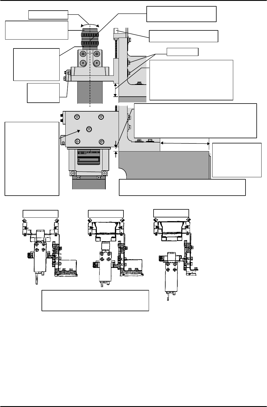
Camera type 3
Camera type 1 Camera type 2
Be sure that the bracket where the CCD
camera is mounted is correctly oriented.
M/C Base
Camera
BKT
Lock bolt
Height adjusting set screw
Camera type 1: 34.5mm
Camera type 2: 21.0mm
Camera type 3: 16.5mm
* These dimensions were
obtained during testing, and
are for reference purposes
Set screw for
camera Q
adjustment
Camera
collar
thickness
Camera 1: 11mm
Camera 2:2.0mm
Camera3: 1.4mm
Lens filter
Camera 1 25mm 1:1.4
Camera 2,3 16mm 1:1.4
Beware for tilt
Aperture and focus lock
screws face this direction
2,8
Camera BKT
M/C Base
Camera
42mm
Camera type 4,7: 25.0mm
(Lens
no.R4013H)
Camera type 4,7: 21.0mm (Lens no.R4034A)
However R4034A
front supply, index camera 7: 15mm
*Reference Value Only
Note: This is the
base end face,
not the module
base contact
surface.
22.0mm for index nozzle & front supply & camera
type 7. *Reference value only.
This bracket
changes when
index nozzle &
front supply &
Camera type 7 is
used. 15mm
lower in conditions
with camera
height different
than above.
FK-9F98-07 QP242E Training Text for Service Engineers
6th edition 6. Proper Data Measurement [8/20]
Fuji Machine Mfg. Co., Ltd. Okazaki
SMT Equipment Quality Assurance Dept.
Technical Support Div. Section No.2
6-8
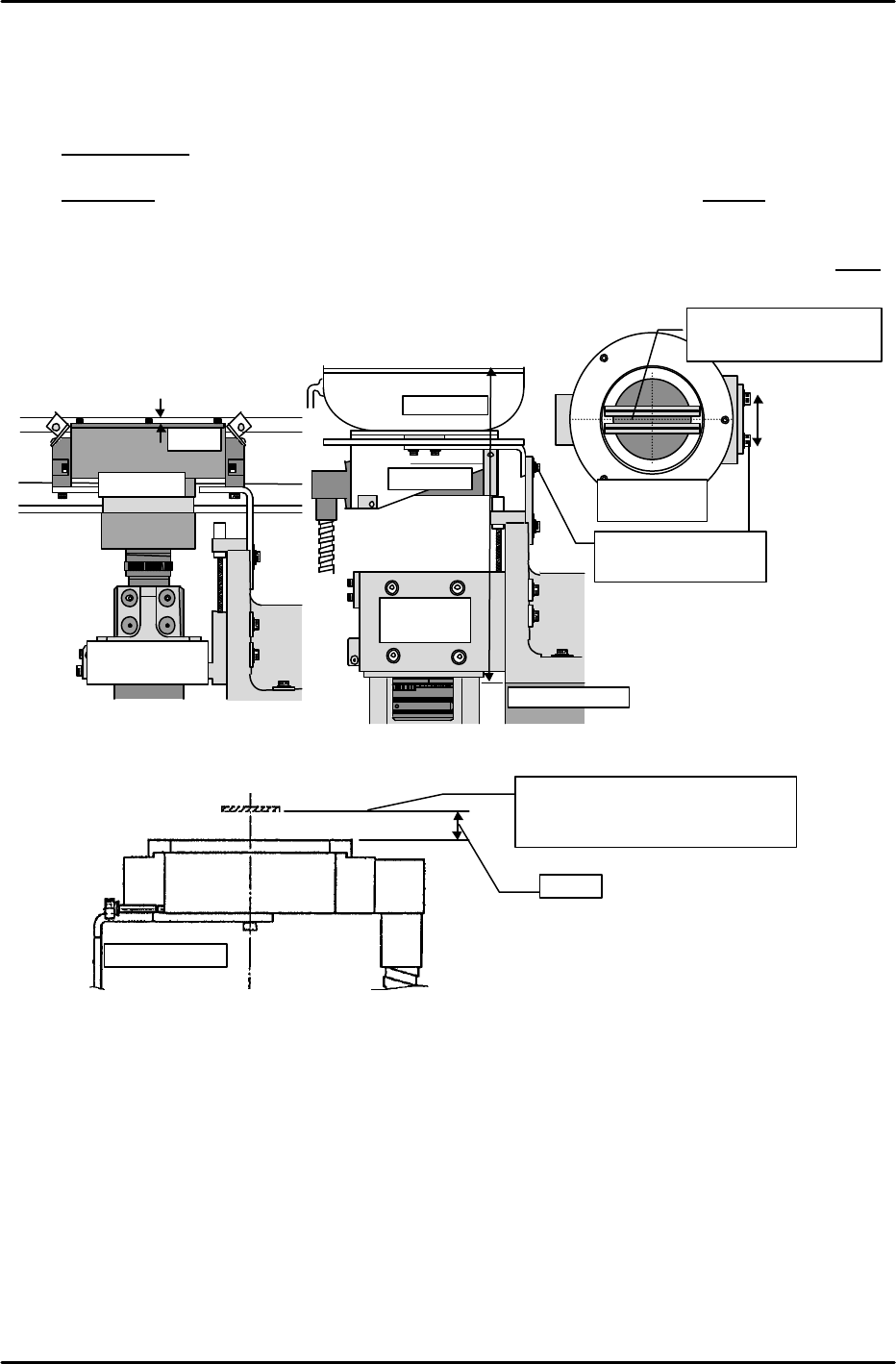
[6-11 ] Adjusting the Parts Camera Lighting Position
1) For camera types 1 to 3:X-direction: Not adjustable Y-direction: Camera center Z-direction:
Adjust so that the top of the light bracket is 2mm below the top of the conveyor bracket.
(Beware of tilt.)
2) For camera type 4 (line scan camera):
X-direction: Not adjustable Y-direction: Camera center
Z-direction: Use a height jig to adjust so that the top of the light cover’s glass is 209mm from
the top face of the machine base. (Beware of tilt.)
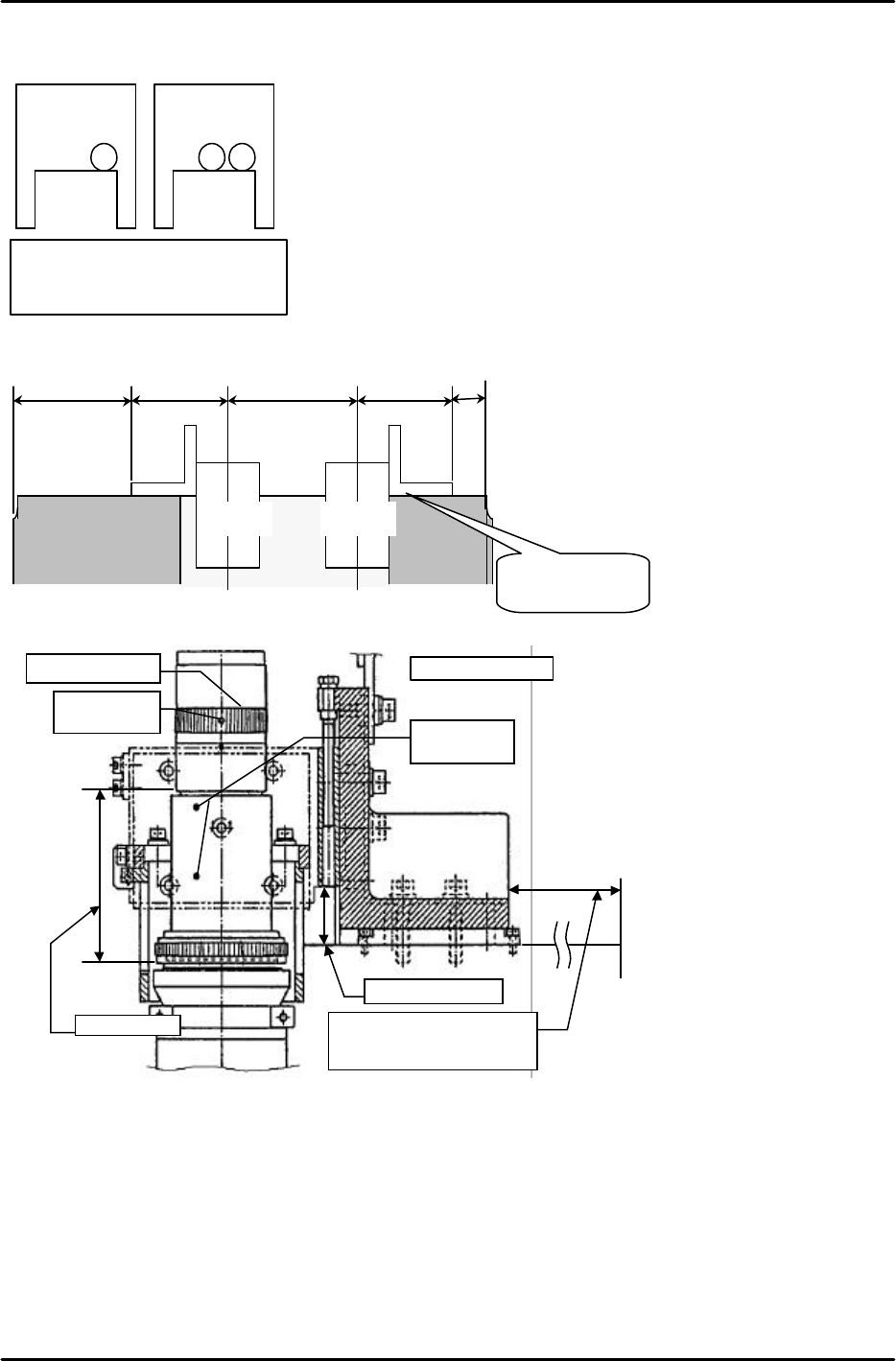
1
2
MFU or
MTU side
2
camera
1
MFU or
MTU side
1 camera
Camera mounting positions in 2-camera systems
Cameras are mounted in the positions shown at left. At 2-camera systems, the
cameras are arranged in the same manner as the device numbers. At camera
systems, the camera is mounted on the right side as viewed from the MFU.
Generally speaking, the camera is not mounted on the left side.
Moreover, unless an on-site modification has occurred, the camera with the
higher camera type number is mounted at the No.2 side.
Camera light source arrangement in 2-camera systems
CCD + CCD: Light sources are located directly below both cameras.
CCD + LINE: The CCD camera’s light source is located directly below the CCD
camera, and the line scan camera’s light source is located on the column (inside
the FRP cover at top of module).
LINE + LINE: The light source for the camera at the No.2 side is located below
the camera, and the light source for No.1 side camera is located on the column.
Power supply of the camera light source arrangement in 2-camera systems
No.2 side camera is located in the PLN control board, and No.1 side is located on
the column.
The camera arrangement is as shown
above (as viewed from MFU or MTU)
at both front and rear parts-supply
machines.
Camera mounting dimensions in 2-camera systems
(with 600mm module)
Camera 1 – camera 2 : A - B
CCD - CCD :135mm-144mm (ABHGC9110)
CCD - LINE :135mm-144mm (ABHGC9100)
LINE - LINE :124mm-155mm (ABHGC9120)
* For 800mm modules, dimension “A” is lengthened.
Other dimensions are unchanged.
Adjust camera type 6 as shown in
the illustration at left. Note that
dimension “B” (focus) is factory
adjusted and does not usually
require further adjusting.
However, if a suitable focus and
resolution cannot be obtained,
change dimensions “A” and “B” as
required.
A:25.43mm
B
:74.85mm
Aperture: fully open
Aperture locking
set screw
Focus locking
set screw
Camera type 6
For type 706: 65mm
For others: Refer to above
Camera 1 Camera 2
Center of the
camera
136mm136mm BA
42
mm
Measured from
module’s base end
surface.
Center of the
camera
FK-9F98-07 QP242E Training Text for Service Engineers
6th edition 6. Proper Data Measurement [9/20]
Fuji Machine Mfg. Co., Ltd. Okazaki
SMT Equipment Quality Assurance Dept.
Technical Support Div. Section No.2
6-9
3) For camera type 6 (line scan camera):
X-direction: Not adjustable Y-direction: Camera center
Z-direction: Adjust so that the top of the fiber ring light is 8mm from the nozzle end (at
vision processing height). (Beware of tilt.)
4) For camera type 7 (line scan camera):
X,Y directions: Align the centers of the double ring fiber light and the fluorescent ring light.
Align the camera center with the center of the lighting unit.
Z-direction: Adjust so that the top face of the fluorescent ring light is 2.2mm apart from
the double ring fiber light. (Adjust so that the top face of the fluorescent ring
light is a little bit higher than the bottom face of the double ring fiber
bracket.) Also adjust so that the top face of the double ring fiber light is 3mm
from the nozzle end (at vision processing height). (Beware of tilt.)
Conveyor top
2mm
Light unit
Camera type
1,2,3
2,8
Camera
type 4
Light unit
M/C base top
★
Y-direction
adjusting bolt
Align camera center
with light unit center
From top of
camera unit
209mm
8mm
Camera type6
Image acquisition height
Nozzle end position when image is
acquired at a 0mm parts height.