QP-242E 工程师培训手册 (6.0).pdf.pdf - 第98页
FK-9F98-07 QP242E Training Text for Service Engin eers 6th edition 11. Coplanarity Check Adjustment & Operation Check [ 4 / 4 ] Fuji Machine Mfg. Co., Ltd. Okazaki SMT Equipment Quality Assurance Dept. Technical Supp…

FK-9F98-07 QP242E Training Text for Service Engineers
6th edition 11. Coplanarity Check Adjustment & Operation Check [3/4]
Fuji Machine Mfg. Co., Ltd. Okazaki
SMT Equipment Quality Assurance Dept.
Technical Support Div. Section No.2
11-3
[11-10 ] Proper Data Measurement
1) Transmit the program created for measuring Proper data to the foreground of the machine.
The program can also be transmitted to the background but it must then be changed to the
foreground prior to the start of measurement. If a suitable program is not used the jig
cannot be positioned via vision processing.
(1) Part data
Enter the jig plate X and Y dimensions (X & Y = 28mm) as the Body size X and Y values.
Enter the jig plate thickness (h = 0.7 mm) as the Component height. Select the Lighting
and Vision type to match the camera type.
Lighting CCD=0, LS=3
Vision type CCD=10, LS=250
Enter Copla_PROP_I or S as the nozzle name.
(2) Nozzle data
Set so that nozzle check is not performed.
(3) Production program
Set the part data specified in (1) above for the first device used in the first sequence.
2) If work is continued from section 13.9 and the jig plate has already been picked, then install
the nozzle to be used if necessary and execute the following work.
Carry out the following command operation to turn on the vacuum and enable the START
ready status; [SET] (F5), [PROPER] (F3), input the ID code?, select the Mod No.?, [ETC] (F5),
[COPLA] (F3). Note that the [COPLA] (F3) command will only display if Coplanarity
Check is set to “1” (Yes).
Next, pickup the jig plate if necessary. The tip of the nozzle should be directly above the
cavity in the plate at this time. Furthermore, the plate should be picked in a status subject
to as little rotation deviation as possible.
3) Move the placement head to the position that satisfies the conditions given below in order to
set a position that is suitable for Proper data measurement. Directly input the provisional
Proper data value using [SET] (F1). Be careful that the sensor head does not make contact
with the jig during the course of this work.
(1) Y-direction Near the center of the sensor head (visual check)
(2) Z-direction Near the middle between the sensor head beam emitting mechanism
and the beam reflector (visual check)
(3) X-direction Within 400 pulses toward the rear from the red LED ON/OFF position
4) Press START to begin automatic measurement.
Repeat measurement twice in the order given below to complete measurement.
Vision process jig plate à Measure in X-direction à Measure in Y-direction
5) Once measurement is completed remove the jig plate from the nozzle holder and remove the
nozzle used for measurement and then cut the vacuum off using either the I/O command or
the part reject command to complete the work.

FK-9F98-07 QP242E Training Text for Service Engineers
6th edition 11. Coplanarity Check Adjustment & Operation Check [4/4]
Fuji Machine Mfg. Co., Ltd. Okazaki
SMT Equipment Quality Assurance Dept.
Technical Support Div. Section No.2
11-4
***** This page does not contain any contents.
FK-9F98-07 QP242E Training Text for Service Engineers
6th edition 12. Placing Pressure Control Function Adjustment [1/4]
Fuji Machine Mfg. Co., Ltd. Okazaki
SMT Equipment Quality Assurance Dept.
Technical Support Div. Section No.2
12-1
[CHAPTER 12] Placing Pressure Control Function
Adjustment
12-1] Prior to Adjusting the Placing Pressure Control Function
- Certain parts require additional pressure compared to normal placement. In order to make it
possible to place this type of part the machine is equipped with a placing pressure control
function in order to control the pressure exerted on parts during placement.
- In the normal part placement operation on the QP242, parts are lowered in one motion from a
height of 9 mm (bottom of the part to the board surface) to a position pushed 0.3 mm into the
board. The pressure at which the nozzle presses the part into the board at this time is
determined by adding various frictional resistances to the pressure of the spring. In general
this can be considered as a primary linear addition that depends on the amount of pushing force
(flexibility of the spring). This linear angle and intercept are obtained beforehand (Proper data
measurement) and the pushing force is calculated from the specified placing pressure when a
part is actually placed. The placing pressure control function, by using this pushing force as an
offset when a part is placed, can be used to control the pressure at which a part is pushed into the
board.
- Additional pressure range : 120 ~ 1200 g
Additional pressure deviation : 3 sigma 10 g
[12-2] Proper Data Settings and Transmission
1) Set the following Proper data item and program nozzle data in F4G for each module and then
transmit the data to the machine.
Proper data : PLM? PPC_Port
2 : Set the port number of the SCU port to which connection is made
from the PPC.
Nozzle data : Nozzle_Type
64 : Set the nozzles that use placing pressure control. (Add to the
original value.) (Set all nozzles during adjustment if there is no
setting from the user. Nozzle names must also be specified.)
2) After transmission of the Proper data to the machine is completed, cut the power to the
machine and reboot.
3) After zero set is completed then begin adjustment
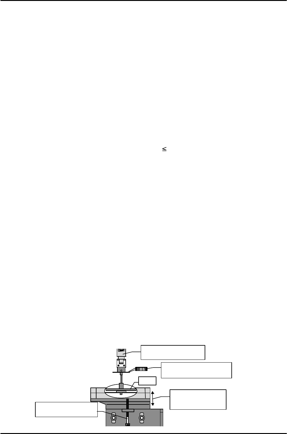
[12-3] Placing Pressure Control Device Height Adjustment
1) Loosen the bolt for adjusting the height of the control device and lower the device as far as
possible.
2) From the previously measured PPC_Cali_Pos_X & Y position, lower the Z-axis to the Proper
data Placment_Height_Z0 position, and set a dial gauge on the top of the nozzle light emitting
surface.
3) Slowly raise the control device using the bolt on the bottom of the control device to find the
position at which the dial gauge begins moving.
4) From the position at which the dial gauge begins moving, secure the device in place at a height
within ± 0.1 mm.
X,Y-axis = PPC_Cali_Pos.
Z-axis = Z0
Move the unit up and
down until the dial
reads zero.
Adjust the height
using the set screw.
Plate
Set the dial gauge on the
light-emitting surface.