QP-242E 工程师培训手册 (6.0).pdf.pdf - 第127页
FK-9F98-07 QP242E Training Text for Service Engineers 6th edition 14. Obtaining a Trace List with PC [ 1 / 2 ] Fuji Machine Mfg. Co., Ltd. Okazaki SMT Equipment Quality Assurance Dept. Technical Support Div. Section No.2…

FK-9F98-07 QP242E Training Text for Service Engineers
6th edition 13. MTU 71E Adjustment [24/24]
Fuji Machine Mfg. Co., Ltd. Okazaki
SMT Equipment Quality Assurance Dept.
Technical Support Div. Section No.2
13-24
Use a dummy tray that satisfies the following conditions.
• Vacuum pressure differential of approximately 2 to 3 (mmHg) between the all leak status
and the tray picked status
• Tray that does not drop as a result of its own weight
As an example consider using the following as a dummy tray.
• Styrofoam: Size 270 mm length x 130 mm width x 30 mm thickness approximately 15 g
Prepare two pieces each with 18 holes that have an inner diameter of 23 mm
(Total weight of about 35 g)
This styrofoam is used for the nozzles that have been shipped.
Overlap the two pieces of styrofoam and pick with the remover (pick the styrofoam so that
the hole near the center of the styrofoam is close to the center of the remover). Adjust the
two pieces of overlapping styrofoam so that the vacuum pressure differential between the
all leak status and the styrofoam picked status is about 2 to 3 (mmHg). (Use the styrofoam
holes as slits.)
Try using the styrofoam pieces adjusted in this way as a dummy tray.
[13-60] Reverse Transmission of Proper Data
1) After all of the Proper data items have been measured transmit the Proper data from F4G.
2) Recheck the transmitted Proper data and input suitable values for any Proper data items
that require revision.
After verifying the Proper data, transmit the Proper data again from F4G to the machine.

FK-9F98-07 QP242E Training Text for Service Engineers
6th edition 14. Obtaining a Trace List with PC [1/2]
Fuji Machine Mfg. Co., Ltd. Okazaki
SMT Equipment Quality Assurance Dept.
Technical Support Div. Section No.2
14-1
[Chapter 14] Obtaining a Trace List with PC
・[14-1] Summary
This section introduces the procedure to save the QO242 E trace list in the PC, in which
NTCC is installed, as a text file, instead of printing out by a printer.
・[14-2] Equipment
1.PC with windows and NTCC installed
2.Digital board(FUJI recommends a RS232C wide board) However, if RS232C(COM)
port for PC itself is used, a digital board is not necessary.
3.A transmission cable to connect QP242E and PC
EEHH1041(15m 25PIN−25PIN when using a digital board COM port )
EEHH1051(30m 25PIN−25PIN when using a digital board COM port )
EEHH1061(15m 9PIN−25PIN when using a PC COM port )
EEHH1071(30m 9PIN−25PIN when using a PC COM port )
The transmission cable used at present is also acceptable.
( Caution: A transmission cable used for MCS-C/C is not acceptable. )
4.QP242E connected to NTCC, which is the target machine to take trace.
5.A floppy disk, or another equipment to save the trace data.
・ [14-3] QP242E Setting
1. Disconnect the cable that is plugged to RS232C ch1 at the CPU board, and plug it to
RS232C ch2 at the CPU board.
2.Plug the transmission cable to DATA CONNECTOR placed behind ICM at QP242E
side.
(If you want to use the cable used as the transmission cable at present, cable
replacement is not necessary. Just keep the cable as the current condition.)
・ [14-4] PC Setting
1.Plug the transmission cable for PC side to the port which is not used for NTCC .
(If you want to use the cable used as the transmission cable now, plug the cable to
the port that is not used for NTCC. However, in case there is no empty port, keep
the cable at the current position.)
* When using the port used for NTCC, close the NTCC. However, by closing the
NTCC, other M/C production data are not available to trace. When using the port
which is not used for NTCC, closing NTCC is not necessary.
2.For Windows NT3.51
①.Start the communication software in PC.
Select[Program manager ]→[Accessories]→[Terminal]to start it.
②.Select [Setting] in the terminal menu bar. Set the items in the [Port Setting] as
followed.
Bits per second 9600
Data bits 8
parity none
Flow control Xon/Xoff
Stop bits 1
Connect using COM?(Port at PC where the transmission
cable of the target QP242E is connected to.)
③.Select [File]à[Save as], and save the setting condition.
(It is useful to keep the setting conditions for trace port : trace.trm)
FK-9F98-07 QP242E Training Text for Service Engineers
6th edition 14. Obtaining a Trace List with PC [2/2]
Fuji Machine Mfg. Co., Ltd. Okazaki
SMT Equipment Quality Assurance Dept.
Technical Support Div. Section No.2
14-2
3.For Windows NT4.0
①.Start by selecting[Start]→[Accessories]→ [hyper terminal]→[hyper terminal]
②.For connection setting, enter a name (eg trace) and press OK.
③.For connection, select the PC port (COM?) to which the target QP242E
transmission cable for tracing data is connected. Press OK.
④.For port setting, carry out the same procedure with step [2.②], and press OK.
⑤.Select [Fail]à[Save] to save the setting conditions.
( Short cut will be created in [Start]à[Accessories]à[hyper terminals] eg: trace.ht)
・
[14-5] The procedure for obtaining trace lists
1.Operation at PC ( for Windows NT3.51)
①.Start the terminal (If it’s started already, restarting is not necessary.)
②.Select [Fail]à[Open] in the terminal. Open the fail saved at step[2.③].
( If the communication condition has been set already, skip this step.)
③.Select [Transfer]à[Receive fails], and enter a fail name in which the trace list will
be saved. Then select [OK] and it will be waiting for receiving the data.
④.After receiving trace list is completed, select [Disconnect] to close the terminal.
2.Operation at PC (for Windows NT4.0 )
①.Select [Start]à[Accessories]à[hyper terminal] to open the short cut which is saved
at step [3.⑤] at PC setting. (eg :trace.ht)
②.Select [Transfer]à[Text capture] in a menu. Enter the fail name in which trace
list will be saved. Then select [OK] to wait for receiving.
③.When receiving is finished, select [Transfer]à[Capture text]à[Disconnect] to close
the hyper terminal.
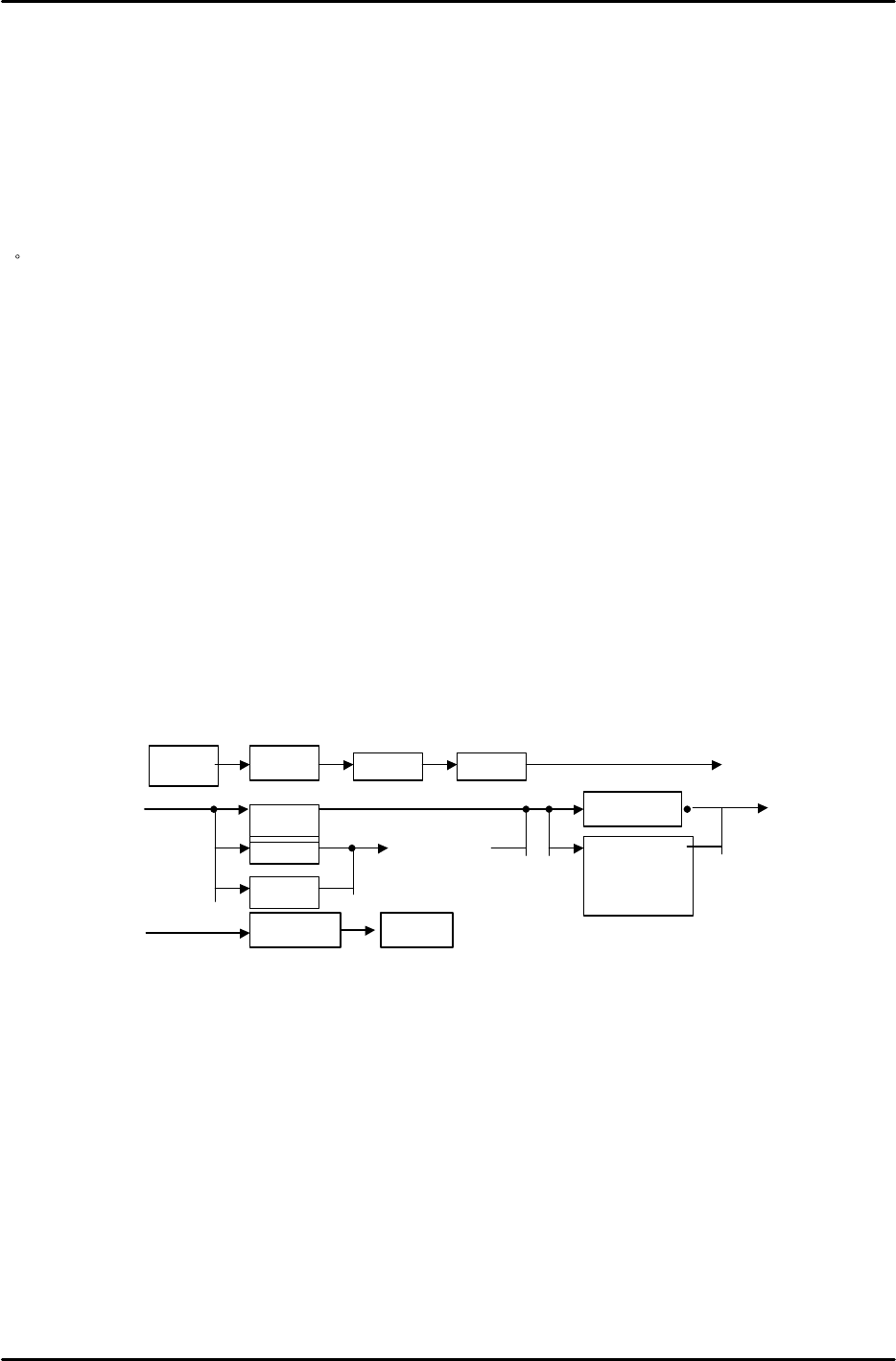
3.Operation at QP 242 E
①. Selecting the place to output. Select RS232C.
②.While the terminal is waiting for receiving data at step[1.③]、[2.②], operate
the above steps to start sending trace data to PC.
③.When sending trace data is completed, plug back the cable that is connected to
RS232C ch2 to RS232C ch1 at CPU board. If the transmission cable has been
replaced to the empty port, plug it back to the original port.
・ Trace data are saved by the method mentioned above with a fail name defined at[The
procedure for obtaining trace lists 1.③、2.②]. Save the data in a floppy or send it
by e-mail.
Set
ETC
Manua
l
Trace
I CM
SCU
PMC
Sel ect
modul e
Communi cati on
l og
Trace l i st
RS232COUT_PUT
A
A
B
B