QP-242E 工程师培训手册 (6.0).pdf.pdf - 第15页
FK-9F98-07 QP242E Training Text for Service Engineers 6th edition 1. QP242E Initial Adjustment (1) [ 6 / 6 ] Fuji Machine Mfg. Co., Ltd. Okazaki SMT Equipment Quality Assurance Dept. Technical Support Div. Section No.2 1…
FK-9F98-07 QP242E Training Text for Service Engineers
6th edition 1. QP242E Initial Adjustment (1) [5/
6
]
Fuji Machine Mfg. Co., Ltd. Okazaki
SMT Equipment Quality Assurance Dept.
Technical Support Div. Section No.2
1-
5
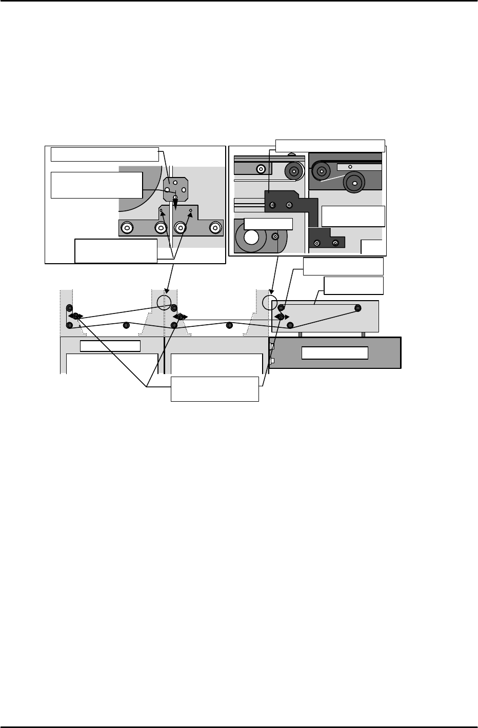
[1-3] Checking the Conveyor Parallelism and Linkage Chain Tension
1) Adjust the conveyor width to the width of a Fuji PCB.
2) Verify that the difference in width from the conveyor's entrance to exit (at each module) is within
0.5mm. Record the measured values on the record sheet.
3) Verify that a linkage bracket is present (for conveyor linkage) at the secondary conveyor rails of each
module.
4) Verify that the linkage chain tension is as prescribed.
Note: If the chain is too tight, the handle will not turn easily.
[1-4] Connecting power cable and an air hose, and transmitting F4G.
*
After ensureing 200V is on in the transformer, connect power cable to power box.
*
*
*
Chain
Sprocket
Conveyor linkage bracket
Insert bracket
between these pins
Slide to back of
bracket
IN conveyor
Last module
Chain tension
adjusting sprockets
IN conveyor
Module 1 secondary
conveyor rail
Conveyor linkage bracket

FK-9F98-07 QP242E Training Text for Service Engineers
6th edition 1. QP242E Initial Adjustment (1) [6/
6
]
Fuji Machine Mfg. Co., Ltd. Okazaki
SMT Equipment Quality Assurance Dept.
Technical Support Div. Section No.2
1-
6
***** This page does not contain any contents.
FK-9F98-07 QP242E Training Text for Service Engineers
6th edition 2. Static Accuracy Measurement [1/2]
Fuji Machine Mfg. Co., Ltd. Okazaki
SMT Equipment Quality Assurance Dept.
Technical Support Div. Section No.2
2-1
[Chapter 2] Static Accuracy Measurement
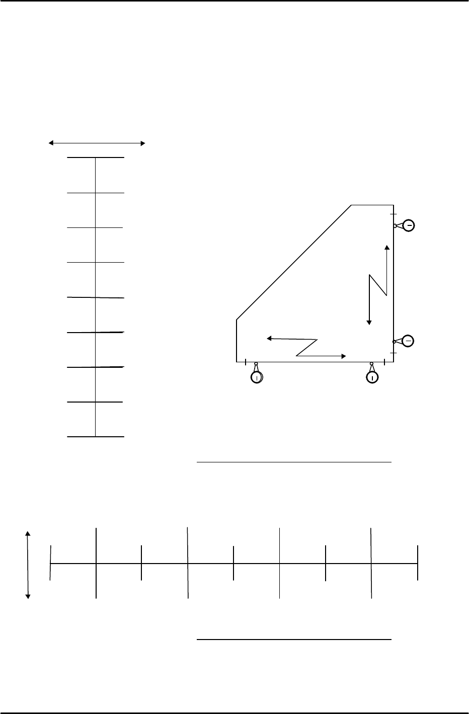
[2-1] X, Y Axes Straightness Measurement
1) Place a right-angled jig on the conveyor in a position that is parallel (approximately) with the X and Y
axes.
2) Mount a dial gauge holder shaft on the end of the placing head, then measure the Y-axis straightness
while moving the head by hand in the Y-direction.
Y-axis movement distance (mm)
Tolerance: 0.03 / 400 (mm) Y-measurement value: / 400 (mm)
3) Measure the X-axis straightness while moving the head by hand in the X-direction.
Tolerance: 0.03 / 400 (mm) X-measurement value: / 400 (mm)
150
50
250
0
100
200
300
350
–
+
X-axis movement distance (mm)
400
0
0
0
0
0
X direction
0
50
100
150
200
250
300
350
+ –
400
0
( )
( )
( )
( )
( )
( )
( )
0
Y direction
0
( )
( )
( ) ( ) ( )
( ) ( )