QP-242E 工程师培训手册 (6.0).pdf.pdf - 第110页
FK-9F98-07 QP242E Training Text for Service Engineers 6th edition 13. MTU 71E Adjustment [ 8 /24] Fuji Machine Mfg. Co., Ltd. Okazaki SMT Equipment Quality Assurance Dept. Technical Support Div. Section No.2 13- 8 [1 3 -…
FK-9F98-07 QP242E Training Text for Service Engineers
6th edition 13. MTU 71E Adjustment [7/24]
Fuji Machine Mfg. Co., Ltd. Okazaki
SMT Equipment Quality Assurance Dept.
Technical Support Div. Section No.2
13-7
[13-19] Provisional Proper Data Transmission
1) Reconfirm that all connection cables are in fact connected to the machine and then turn the
power on.
Note: If the remover station lower limit is not ON, the machine will return a
communications error and will not properly boot up.
2) Open the QP242 Proper data from F4G, set the items required for the MTU71, and verify.
(Example) Set PLM? (number of module to which MTU71 is joined) _Device_Type to "3"
(MTU71).
Enter a suitable value in Original Position TY. (Set a value that does not
exceed Max Limit Position TY.)
Set PLM?_Pickup_remover_Org_X to "-56" and set Pickup_remover_Org_Y to "63".
3) Transmit the Proper data to the machine. Once transmission is successfully completed cut
the power to the machine and then reboot.
[13-20] I/O Check of Each Type of Sensor and Solenoid
Go to the I/O command on the machine and confirm that the following input and output
signals are working correctly.
Input Output
Remover station vicinity X002: RMVR EXIST CHK
X003: RMVR CHUCKING
X00A: REMOVER UP END
X00C: REMOVER DN END
Y005: RMVR UNCHUCK
Y000: REMOVER UP
Y001: REMOVER DWN
Empty tray removal X016: TRAY REMOVE CK Y02B: REMOVER VACUUM
Each interlock sensor X017: TRAY STORE CHK
X01D: TZ MV OK POS2
X03E: TZ MV OK POS1
X03F: TY MOVE OK POS
Tray part pickup position
(Refer to note below.)
X038: CHK(TZ,POS1,2)
X039: CHK(TY,ADD1,2)
Y028: TRAY 1/2 SEL
Y029: REACH/TRAY SEL
NG Parts Conveyor X018: NG PARTS FULL
X019: PARTS CV COUNT Y027: PARTS CONV ON
Other X03C: TZ SPD DWN PNT
X03D: TY SPD DWN PNT
X028: TRAY ORG SW Y02A: TRY ORG LAMP
Remarks: When odd numbered device (1, 3, 5~) input is checked Y028: TRAY 1/2 SEL X
Y029: REACH/TRAY SEL O
When even numbered device (2, 4, 6~) input is checked Y028: TRAY 1/2 SEL O
Y029: REACH/TRAY SEL O
Note: Once checking is completed always return Y029: REACH/TRAY SEL to "X".
FK-9F98-07 QP242E Training Text for Service Engineers
6th edition 13. MTU 71E Adjustment [8/24]
Fuji Machine Mfg. Co., Ltd. Okazaki
SMT Equipment Quality Assurance Dept.
Technical Support Div. Section No.2
13-8
[13-21] Prior to Zero Set Adjustment
Note: Even if zero set has not been completed the inching button will work in relation to the
TZ-axis but only if the TY-axis advance or retract limit sensor is on. If the inching button
is used when the advance limit sensor is on, the TZ-axis interlock sensor will not work.
Exercise caution when using the inching button with the tray holder in the forward status.
If the tray holder or LM guide makes even the slightest contact with the cover or guide
bar the tray will have to be readjusted.
[13-22] Preliminary Zero Setting
1) Remove the TZ-axis zero set dog (also serves as TZ-axis interlock) and TY-axis interlock dog
(long top to bottom dog) from inside the MTU71E unit.
2) Check that the remover has been returned and then with the TY-axis retract limit sensor
and TY-axis interlock sensor in the tripped status, press START on the machine to begin
zero setting.
3) After zero setting of the X, Y, Z, and Q axes on the machine has been completed, zero setting
of the TY-axis and TZ-axis commences in that order. Check that the motor has definitely
begun working, then reset the tripped status of the TY-axis retract limit sensor, and trip the
TY-axis zero set sensor two times (now at the retract limit) to complete zero setting of the
TY-axis. Once zero setting is completed the TY-axis will begin moving to the
Original_Position_TY position so if the Proper data value is to be entered, trip the TY-axis
retract limit sensor again at this time.
4) TZ-axis zero setting will then commence. Check that the TZ-axis motor is working, then trip
the TZ-axis zero set sensor two times and complete TZ-axis zero setting. If the initial display
screen appears on the machine monitor this indicates that zero setting is completed. Since
the next adjustment is initiated from this status, maintain the servo lock status as it is.
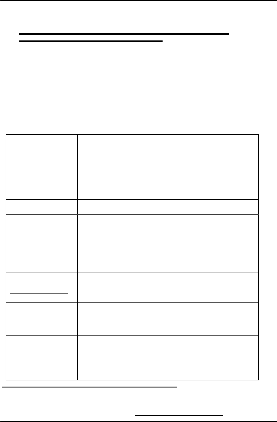
[13-23] TY-axis Zero Set Position Adjustment
Secure the zero set dog in place in the center of the oblong hole. Stretch the timing belt so
that the shuttle is 2 mm from one of the mechanical stoppers. (Belt tension: 52.60HZ ~ 62.60
Hz) Next, move the TY-axis so that it is +167 pulses (15 mm) from the mechanical stopper
(check the servo count while doing this). Move the sensor bracket side to adjust the sensor so
that it comes on in this position. Once adjustment is finished use the servo counter to verify
that the position at which the sensor comes on is within a range from +164 to +170 pulses
(14.76 ~ 15.3 mm) from the mechanical stopper.
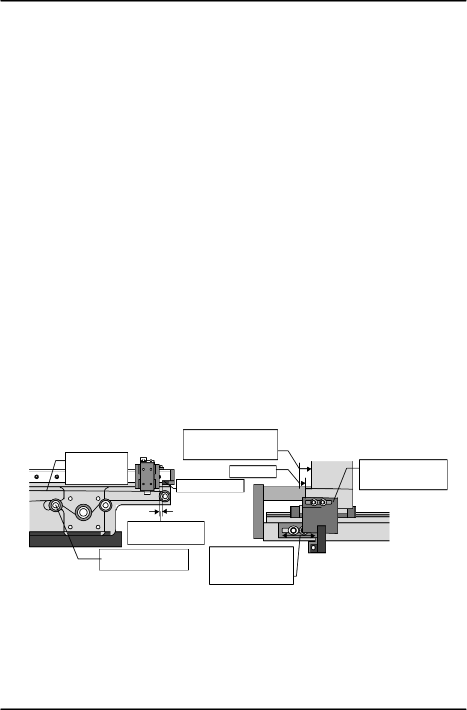
[13-24] Shuttle Assembly Y-direction Angle of Orientation Adjustment
Attach the dial gauge to the placement head, set the dial gauge needle on the side of the shuttle
assembly linear guide rail and measure the angle of orientation in the Y-direction. Adjust the
angle so that the difference from the advance limit to the retract limit is within 0.1 mm.
Mecha-stopper
Adjust the tension
using this pulley.
Pull the belt back
2 mm.
sensor
Adjust so that the
sensor comes on in
a position between
+164 and 170
LM
guide
゙
Mecha-stopper
Secure the dog in
place in the center
of the oblong hole.
Adjust to a position
167 pulses from the
mechanical stopper.
Belt tension
measurement
location
Outside view from the side of the shuttle
Inside view from the side of the shuttle
15mm
FK-9F98-07 QP242E Training Text for Service Engineers
6th edition 13. MTU 71E Adjustment [9/24]
Fuji Machine Mfg. Co., Ltd. Okazaki
SMT Equipment Quality Assurance Dept.
Technical Support Div. Section No.2
13-9
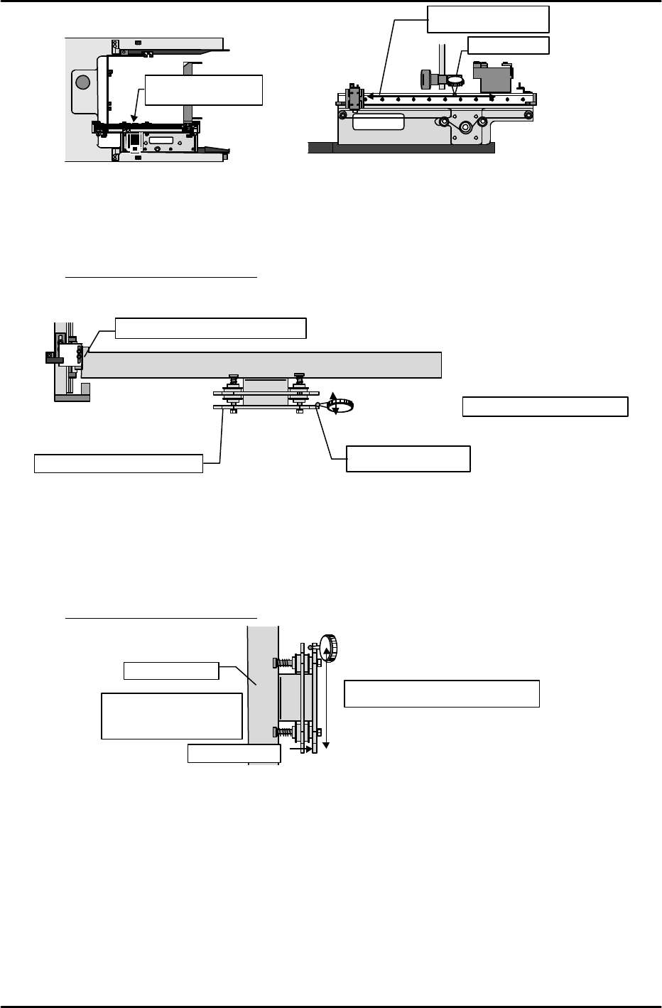
[13-25] Shuttle Jaw Front to Back Angle of Orientation Adjustment
Set the dial gauge needle on the inside surface of the stationary claw and move it up and down
in the Z-direction. Then twist the shuttle bar mount to adjust the jaw so that the angle of
orientation from the top of the claw to the bottom is within the allowable tolerance.
Tolerance: Within +/- 0.1 mm
[13-26] Shuttle Jaw Parallel Adjustment
Use the dial gauge set on the inside of the stationary side claw in the previous item. This time
move the dial gauge in the X-direction to measure the parallelism of the jaw. If the difference at
each end exceeds the allowable tolerance then the shuttle bar must be replaced. When the
shuttle bar is replaced not only must parallel adjustment be performed but the angle of
orientation in the previous item must be adjusted again as well.
Tolerance: Within +/- 0.2 mm
Tolerance : within +/-0.2mm
Advance limit position
from the top of the
shuttle assembly
Shuttle bar
Stationary side
2
1
Measure the side of
the linear guide.
Angle of orientation
within 0.1 mm
Dial gauge
①
②
Inside view from the side of the shuttle
Shuttle bar
Shuttle stationary claw side
Top (
)
Bottom ( )
Measure the side in
the Z-direction
Tolerance : within +/-0.1mm
Fine adjust by the torsion status.
Top (
)
Bottom( 0 )
1
2