QP-242E 工程师培训手册 (6.0).pdf.pdf - 第57页
FK-9F98-07 QP242E Training Text for Service Engineers 6th edition 6. Proper Data Measurement [ 16 /20] Fuji Machine Mfg. Co., Ltd. Okazaki SMT Equipment Quality Assurance Dept. Technical Support Div. Section No.2 6- 16 2…
FK-9F98-07 QP242E Training Text for Service Engineers
6th edition 6. Proper Data Measurement [15/20]
Fuji Machine Mfg. Co., Ltd. Okazaki
SMT Equipment Quality Assurance Dept.
Technical Support Div. Section No.2
6-15
Move to position
where jig can be
inserted smoothly
Set a receiver jig
to No. 1.
Nozzle jig
Changer spring
Nozzle changer unit
Nozzle detection sensor
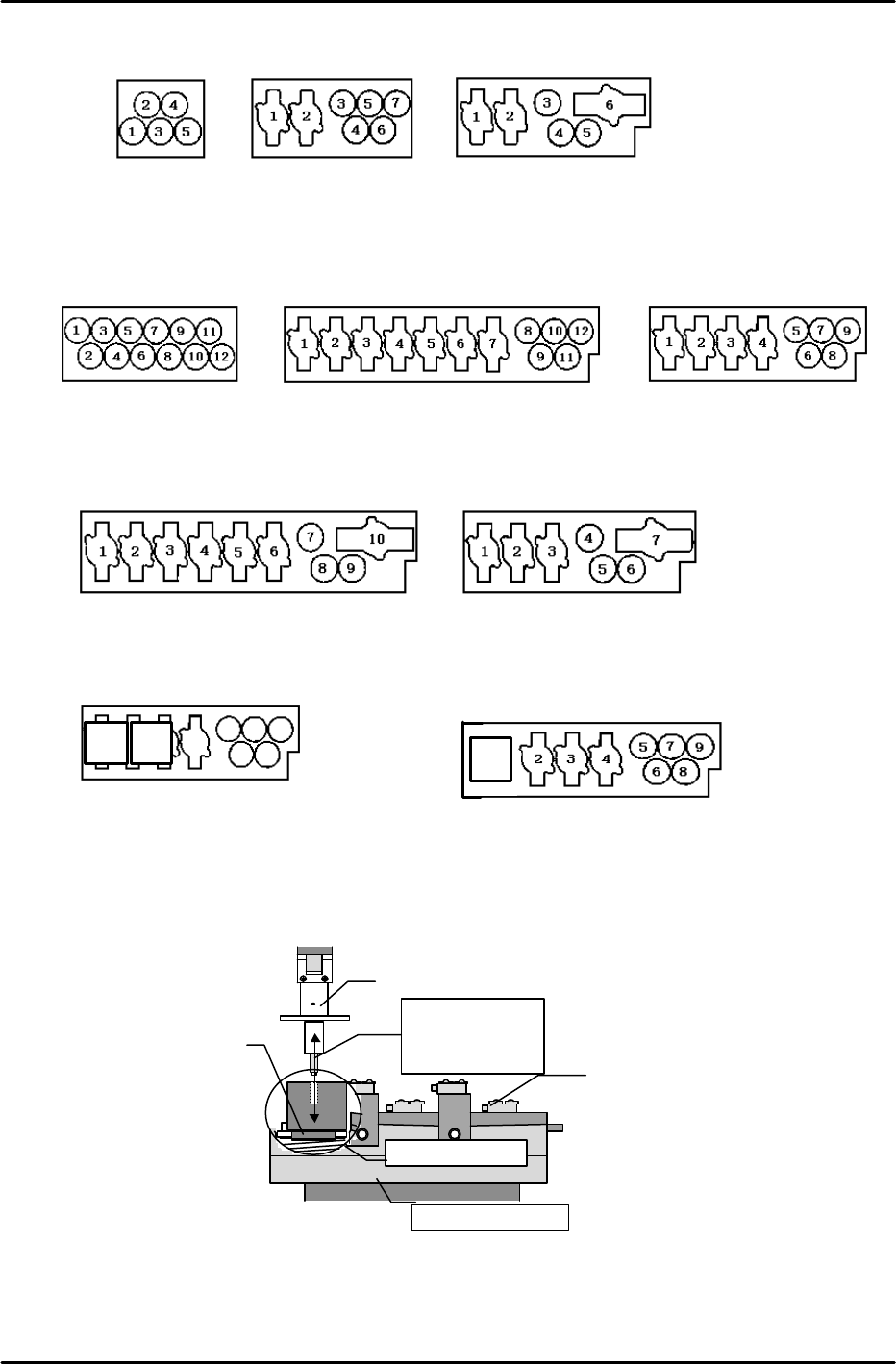
Type A (for 1-camera
and 2-camera systems)
Type B (For 1-camera
systems only)
Type C (for 1-camera
systems only)
5 single nozzles loaded
•5 single nozzles loaded
•2 mechanical chucks
•3 single nozzles loaded
•3 mechanical chucks loaded
*
For 800 Module
Type A12 (for 1-camera and
2-camera systems)
12 single nozzles loaded
Type B1 (For 1-camera systems only)
Type B12 (for 1-camera
and 2-camera systems)
•5 single nozzles loaded
•7 mechanical chucks loaded
•5 single nozzles loaded
•4 mechanical chucks loaded
Type C12 (for 1-camera and
2-camera systems)
Type C1 (For 1-camera systems only)
•3 single nozzles loaded
•4 mechanical chucks loaded
•3 single nozzles loaded
•7 mechanical chucks loaded
Type E12 (for 1-camera and
2-camera systems)
•6 single nozzles loaded (1 of which is for 56mm)
•3 mechanical chucks loaded
1
•7 single nozzles loaded (2 of which are
for 56mm)
Type D12 (for 1-camera
21
3
4
5
6
7
8
FK-9F98-07 QP242E Training Text for Service Engineers
6th edition 6. Proper Data Measurement [16/20]
Fuji Machine Mfg. Co., Ltd. Okazaki
SMT Equipment Quality Assurance Dept.
Technical Support Div. Section No.2
6-16
2) Nozzle_Select_Pos.Z
* Because B1 and C1 types have UP limit stoppers, adjust so that no contact is made with the
stopper before beginning this measurement.
1. After completing all the Nozzle_Select_Pos.X,Y measurements, remove the receiver jig
from the changer and the nozzle jig from the nozzle shaft. Also raise the nozzle station.
2. Mount a nozzle on the nozzle shaft and move the head by hand to the first
Nozzle_Select_Pos.X,Y position of the single nozzle station.
3. Turn the Z-axis pulley by hand to lower the nozzle to the position shown below. This is
the Nozzle_Select_Pos.Z position.
1) For types other than C1 and B1:
•3.5mm spline type : Raise to a position 3666 pulses above the Z-axis Min. Limit.
•2.0mm spline type : Raise to a position 3000 pulses above the Z-axis Min. Limit.
2) For B1 and C1 types:
•3.5mm spline type : Raise to a position 4083 pulses above the Z-axis Min. Limit.
•2.0mm spline type : Raise to a position 3416 pulses above the Z-axis Min. Limit.
* Note that the UP limit for B1 and C1 types is slightly lower due to the stopper adjustment
which is required (see step 5). Therefore, lower the Z-axis and re-measure the
Nozzle_Select_Pos.Z position.
4. Execute the following command sequence to automatically enter the data: [NZZLE
SELECT] à [Zn] à [SET].
5. With the Z-axis at the step 3 position (see above), adjust so that the bottom of the nozzle
disk makes contact with top surface of the nozzle station. Set a dial gauge on the top face
of the nozzle disk and find the exact height at which contact is made with the top face of
the nozzle holder.
* If measuring with a dial gauge, be sure that the gauge is calibrated.
* After adjusting types B1 and C1 as described above, position the UP limit stopper against the
bracket, then turn the stopper another 1/2 a revolution in the bracket direction and lock it there.
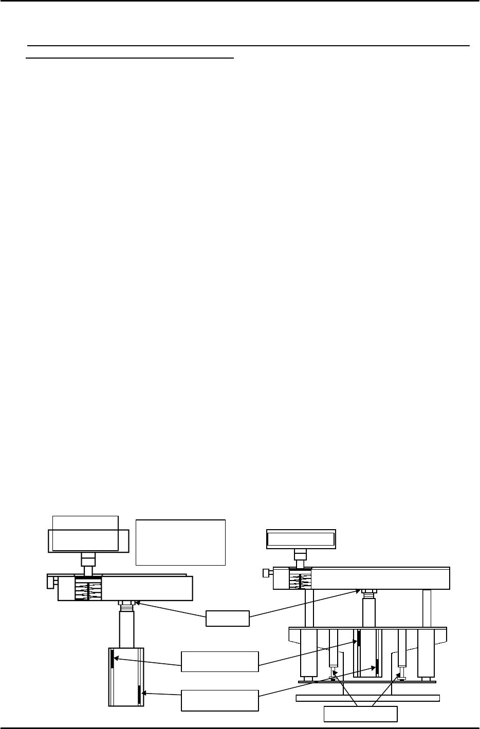
6. With the changer raised, adjust the UP limit sensor. Begin by moving the sensor upward
until it switches off, then lower the sensor to the position where it switches on. Secure the
sensor 1mm below that position. Adjust the DOWN limit sensor by moving it downward
until it switches off, then raise it to the position where it switches on. Secure the sensor
1mm above that position.
7. Finally, verify that all nozzle detection sensors are operating properly. Both the green and
red LEDs should be lit when a nozzle is absent. If a nozzle is present, only the green LED
should be lit. Also use I/O commands to verify that inputs are correct.
Station UP limit
sensor
Station UP limit
sensor
UP limit stopper
Adj. bolt
B1 and C1 types
Types other
than B1 and C1
Note that the type “A”
adjusting bolt is
located on the bottom
FK-9F98-07 QP242E Training Text for Service Engineers
6th edition 6. Proper Data Measurement [17/20]
Fuji Machine Mfg. Co., Ltd. Okazaki
SMT Equipment Quality Assurance Dept.
Technical Support Div. Section No.2
6-17
【
6-20
】
Nozzle_Check_Pos.X,Y,Z (Single Types Only)
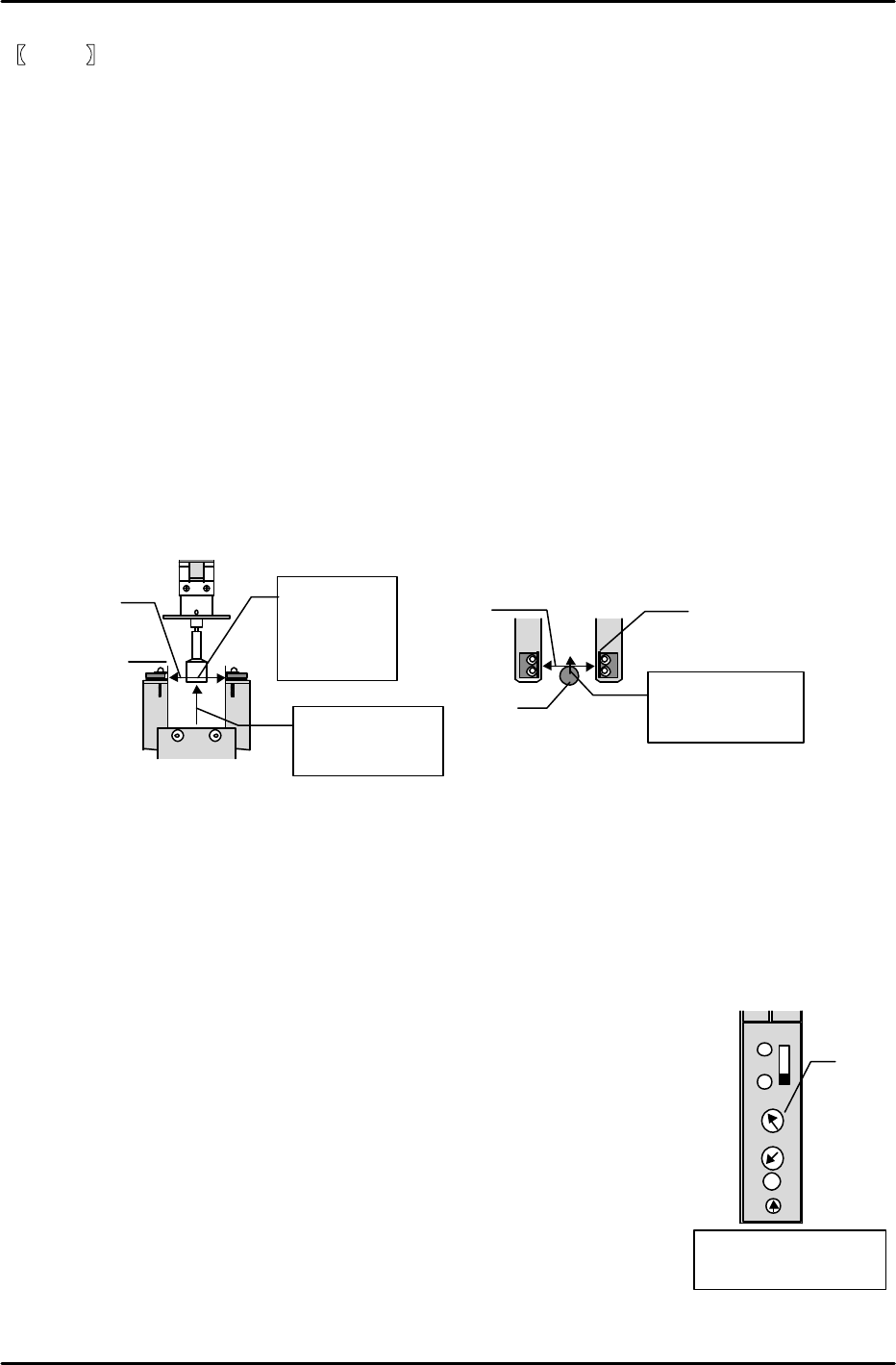
Note: As shown in the figure below, the slits are sandwiched between the sensor and sensor
bracket. Mount so that the sensor emitter and receptor are directly opposite (on a
straight line) the slits (sensor beam aligned). This can be gauged by eye.
1) Mount a 10mm front light nozzle on the single shaft.
2) Turn on the “OUT Y018 NZL CHNGR UP” I/O to raise the nozzle changer unit.
3) Move each axis to the prescribed position and lock the servos.
X-axis: Move the nozzle tip midway (centered) between the nozzle check sensors.
Y-axis: While watching the “IN X00D NOZZLE CHECK” I/O, use the Y-axis
inching button to retract the nozzle. Retract the Y-axis 2000 pulses
beyond the point where the I/O switches ON. (2000P1s = 5mm: nozzle
center)
Z-axis: While watching the “IN X00D NOZZLE CHECK” I/O, use the Z-axis
inching button to lower the nozzle. Lower the Z-axis 1000 pulses beyond
the point where the I/O switches ON. (1000P1s = 1.5mm)
4) After moving each axis to its prescribed position, execute the following command sequence
to automatically enter the data:
[NZZLE SELECT] à [Check Pos.] à [SET].
[6-21] Nozzle_Diameter Check, Adjustment (Single Types Only)
1) After completing the [7-20] adjustment, adjust the sensitivity
of the nozzle sensor amplifier using the following 4 nozzle sizes: 0.7, 1.3, 10, 20.
2) Begin by increasing the amplifier sensitivity until the sensor beam from the emitter side is
received by the receptor side. (The green LED lights when the sensor beam is received.) If the
sensor beam is not received even when the sensitivity is increased, adjust the sensor and slit
positions until the sensor beam is received.
3) Verify that the 4 nozzle types listed above are present at the nozzle changer.
(The “NOZZLE TYPE” item must be “1”.)
[Nozzle data settings in program]
Module/Head# à Enter the module number.
Nozzle No. à Enter the nozzle number.
Size X à Enter the nozzle diameters.
Size Y à Enter the nozzle diameters.
BackLight Size X à 300
BackLight Size Y à 300
Nozzle Type à 1
Nozzle Length à 0
4) Begin by performing a nozzle change in order to mount a 10mm nozzle at the head.
Sensor beam
Z-axis
1.5mm (1000
pulses) below
nozzle bottom
face
X-axis
Centered between
sensors
Sensor
Nozzle
Y-axis
2000 pulses from
sensor on position
Slit
Slit
OUT
TIME
SEC
Located beside nozzle
changer (left side)
5
Use this
volume to
adjust the
sensor
ALM