QP-242E 工程师培训手册 (6.0).pdf.pdf - 第60页
FK-9F98-07 QP242E Training Text for Service Engineers 6th edition 6. Proper Data Measurement [ 19 /20] Fuji Machine Mfg. Co., Ltd. Okazaki SMT Equipment Quality Assurance Dept. Technical Support Div. Section No.2 6- 19 […

FK-9F98-07 QP242E Training Text for Service Engineers
6th edition 6. Proper Data Measurement [18/20]
Fuji Machine Mfg. Co., Ltd. Okazaki
SMT Equipment Quality Assurance Dept.
Technical Support Div. Section No.2
6-18
5) Next, perform a nozzle size check by executing the following command sequence: [SET] à
[POSITION] à [Select Module] à [NOZZLE] à [CHECK] à [START].
Adjust the sensor amplifier volume (located to the left of the nozzle changer) until the
measured value is within 10000 +/- 150.
6) Perform about 20 nozzle size checks, verifying that there are no significant fluctuations in the
measured values. (Guideline: +/-10 )
7) Repeat the above steps for nozzle sizes 0.7, 1.3, and 20, and adjust so that the size check
results for all 4 nozzles are within +/-150.
If not, repeat the sensitivity adjustment with that nozzle mounted. When adjusted to within
+/-150, repeat step 6 (above) for the remaining 3 nozzles.
[6-22] Nozzle Change Operation Check
1) Mount the user nozzles in all of the index holders and single nozzle changers, verifying that
nozzle changes occur properly at every position and with every nozzle size.
2) Also verify that the nozzle size check sensor (for single nozzle changers) operates properly
with the user nozzles.
3) Verify that operation also occurs properly with the spares.
[6-23] Parts_Eject_Pos_X,Y
1) Mount a 10mm nozzle in the holder.
2) Lock the servo at the position where the reject box center is aligned with the nozzle center.
3) This is the Parts_Eject_Pos_X,Y position. Execute the following command sequence to
automatically enter this data:
[ETC] à [REJECT POS.] à [REJECT BOX] à [SET].
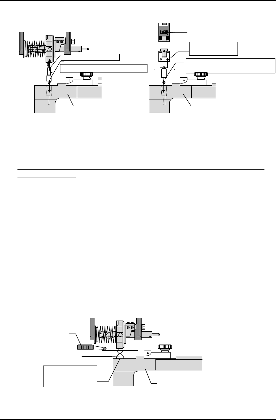
[6-24] Device_Origin_IPD0_X,Y
* Measure all MFUs at module 1, then use the MFU where the measured result was closest to
the average value to measure all modules. This measurement should also be performed at
modules with MTUs.
1) Connect the MFU to the module which is being measured.
2) Place a device jig at the MFU’s D1 position.
3) Mount a nozzle jig (for the device jig) in the holder.
4) Turn off the 200V power supply, then move the head by hand to find the position where the
nozzle jig can be inserted smoothly into the device jig hole. Lock the servo at this position. (Do
not force the nozzle jig into the hole if it cannot be inserted smoothly.)
5) Execute the following command sequence to automatically enter the data: [DEVICE] à
[ORG.POS.X/Y] à [SET].
* The Proper data value is the average value for all MFUs.
6) Turn off the 200V power supply, raise the Z-axis by hand to extract the nozzle jig from the
device jig hole.
FK-9F98-07 QP242E Training Text for Service Engineers
6th edition 6. Proper Data Measurement [19/20]
Fuji Machine Mfg. Co., Ltd. Okazaki
SMT Equipment Quality Assurance Dept.
Technical Support Div. Section No.2
6-19
[6-25] Pickup_Height_IPD_Z0
* If measuring with a dial gauge, be sure that the gauge is calibrated.
* Measure all MFUs at module 1, then use the MFU where the measured result was closest to
the average value to measure all modules. This measurement should also be performed at
modules with MTUs.
1) Mount a 10mm adjusting nozzle in the holder.
2) Place a device jig at the MFU’s number 1 position (left end).
3) Lower the Z-axis until the bottom of the nozzle makes contact with the surface of the device
jig which was mounted at the previous step. At this position, set a dial gauge on top of the
nozzle disk.
4) Slowly lower the Z-axis to find the point where the dial gauge begins to move.
5) The point where the dial gauge begins to move is the Z0 position. Execute the following
command sequence to automatically enter this data (Pickup_Height_IPZ0): [DEVICE] à
[ORG.POS.Z] à [SET].
6) Place the device jig at the MFU’s number 21 position (right end), then repeat steps 3 and 4
above to verify the Z0 position.
7) Verify that the positional difference between the MFU’s number 1 and number 21 (number 31
at 800mm module) positions is 46 pulses or less.
* The Proper data value is the average value for all MFUs (numbers 1 and 21, or numbers 1
and 31).
Device jig
Dial gauge
10mm nozzle
Position where
nozzle is in contact
with the jig.
Device jig
Jig for Index type
Position where insertion is smooth
Index jig
Device jig
Jig for single type
Position where insertion is smooth
Nozzle shaft
Single jig

FK-9F98-07 QP242E Training Text for Service Engineers
6th edition 6. Proper Data Measurement [20/20]
Fuji Machine Mfg. Co., Ltd. Okazaki
SMT Equipment Quality Assurance Dept.
Technical Support Div. Section No.2
6-20
[6-26] Mark Camera Repeat Reading Accuracy
1) Transmit the program used for the placing accuracy measurement (see chapter 9) to the
machine.
2) Adjust the conveyor width to accommodate a PCB which is appropriate for the program, then
place the PCB at the IN conveyor.
3) In the step operation mode, specify sequence number 1, then press the START button to load
the PCB.
4) After the PCB is clamped, mark reading begins with the head positioned at the specified
coordinates. When mark reading is completed, the mark’s deviation amount displays at the
monitor and the START button is enabled.
5) Record the first reading result.
6) Specify the number 1 sequence again and record the displayed reading result.
7) Repeat this procedure 5 times for the same sequence.
8) Take the difference between the maximum and minimum recorded reading results and
calculate the X and Y direction deviations. Tolerance: 10 (0.01mm) or less
9) After performing an idling operation for 30 hours, repeat steps 1 through 8 above.
* Use only PCBs with good-condition marks when performing the above measurements.
[6-27]
After completing all the required procedures (described above) at all the modules,
proceed to the next chapter.