QP-242E 工程师培训手册 (6.0).pdf.pdf - 第88页
FK-9F98-07 QP242E Training Text for Service Engineers 6th edition 10. STU Adjustment & Operation Check [ 2 /8] Fuji Machine Mfg. Co., Ltd. Okazaki SMT Equipment Quality Assurance Dept. Technical Support Div. Section …

FK-9F98-07 QP242E Training Text for Service Engineers
6th edition 10. STU Adjustment & Operation Check [1/8]
Fuji Machine Mfg. Co., Ltd. Okazaki
SMT Equipment Quality Assurance Dept.
Technical Support Div. Section No.2
10-1
[CHAPTER 10]
STU Adjustment & Operation Check
[10-1] Prior to Adjusting the STU
STU-1 Specifications
Number of part types : 1 type per unit
Tray size : 100 x 150 mm ~ 150 x 330 mm
Tray stacking height : 4 ~ 50 mm
Max Empty Tray Weight : 240 g/tray
Occupied devices : 9 devices
Number of units that can be loaded: MFU-5 1 (0) MFU-58 2 (1)
- The values in parentheses indicate the number of STUs that can
be loaded on an MFU when a 2-camera system is used.
STU-2 Specifications
Number of part types : 1 type per unit
Tray size : 50 x 50 mm ~ 102 x 102 mm
Tray stacking height : 4 ~ 50 mm
Max Empty Tray Weight : 240 g/tray
Occupied devices : 7 devices
Number of units that can be loaded: MFU-5 2 MFU-58 4
- There are no restrictions when a 2-camera system is used.
- The STU able to stack trays and for this purpose is equipped with a unit to raise trays and a tray
remover.
- Trays are always positioned with a top surface reference using the positioning sensor. As a result
part pickup using the pickup nozzle does not have to take into account such things as the part
height, tray thickness, and number of trays depending on the pickup nozzle.
- Since STU units can be loaded on an MFU it is possible for a mix of STU and IP-type feeders to be
loaded on a module. However, it is not possible to load two different types of STUs on the same
module since this would create two STU mechanical standards.
- Since there is spacing (3 device positions) on both sides of the STU to avoid interference with IP
feeders, it is recommended that the STU be loaded on the left side of the MFU and that an
accompanying reject parts conveyor be loaded on the right side of the STU.
- An independent air source is required on the STU.
FK-9F98-07 QP242E Training Text for Service Engineers
6th edition 10. STU Adjustment & Operation Check [2/8]
Fuji Machine Mfg. Co., Ltd. Okazaki
SMT Equipment Quality Assurance Dept.
Technical Support Div. Section No.2
10-2
[10-2] STU Loading
1) Cut the power to the machine.
2) After checking the STU type and module specified for loading in the specification manual, set the
STU in the MFU (D9). Also connect the STU coupler connector part request cable to the device
number 9 connector and the tray out cable to device number 8.
3) Load the MFU in the machine being careful of the cables. After the MFU is loaded, connect the
STU power cable and air tubing.
4) Once the cables are connected turn the power to the machine on and verify that the [POWER ON]
lamp on the rear of the STU is lit
[10-3]
Proper Data Check
After checking the following Proper data items transmit the Proper data to the machine and
then reboot the machine.
Module Proper data
* PLM? Device Type
0: Recognize IP type feeders
* PLM? STU_Type
0: Compatible with a Y-direction length of up to 250 mm (STU2)
1: Compatible with a Y-direction length of up to 330 mm (STU1)
* PLM? IPDO_X, Y, Z
Go to section [6-24& 25] and enter the measured values.
When entering the Proper data items above, if Package_Type in the Package_Edit data of the
placement part is set to “0”, the machine will recognize parts supplied from an STU.
[10-4]
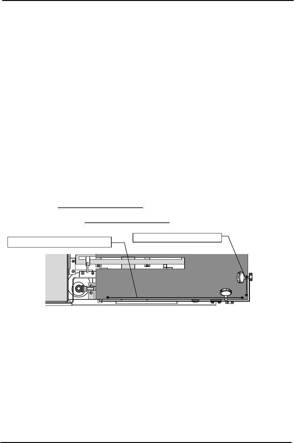
Tray Positioning Side Plate Parallel Measurement
1) Set a dial gauge on the placement head, move in the Y-direction and measure the side steel plate.
Tolerance: Within 0.5 mm
2) Set the dial gauge in the same way, move in the X-direction and measure the front steel plate.
Tolerance: Within 0.3 mm
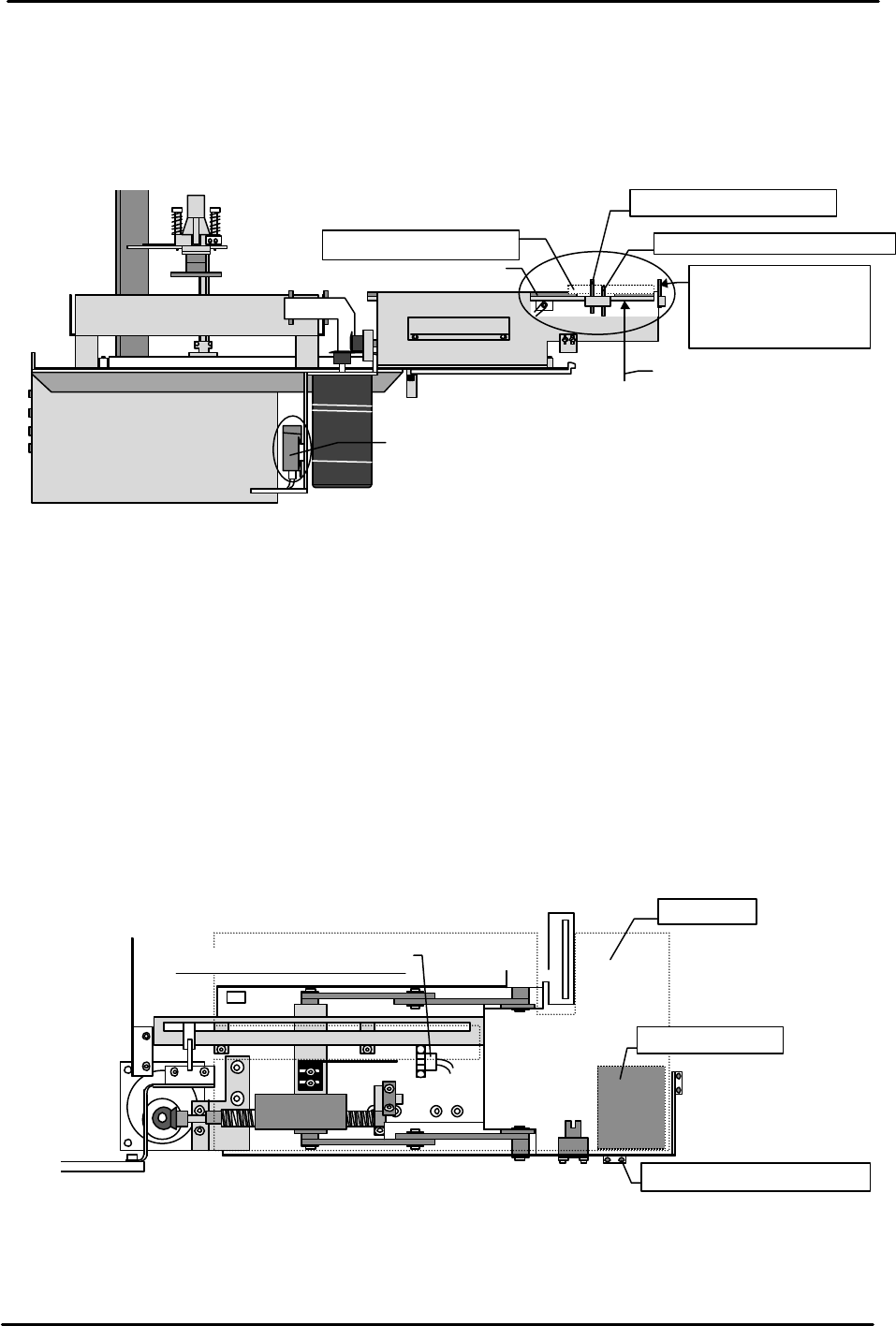
[10-5] Tray Position Check Sensor & Add Check Sensor Adjustment
1) After connecting the STU cable and air tubing, the STU power will come on when the machine
power is booted up.
2) Adjust the tray position check sensor and add check sensor light beams so they are aligned at the
provisional heights by loosening the sensor mount hollow bolts and moving the sensors up and
down. Check the servo amps while doing this. Temporarily adjust the sensors so that the height
of the add check sensor is higher than the tray position check sensor.
3) Load a standard 100-pin size empty tray (used when acquiring data) on the STU tray holder and
then load the device jig used for Proper data measurement next to the STU at device position
number 11.
4) When the I/O Y02D SEND PART D9 of the loaded module is turned on, the tray holder rises, the
top of the empty tray set in the previous step is detected by the tray position check sensor and the
holder then stops.
①②
3.
4.
Measure parallelism with the Y-axis
Measure parallelism to the X-axis.
( )
( )
( )
( )
FK-9F98-07 QP242E Training Text for Service Engineers
6th edition 10. STU Adjustment & Operation Check [3/8]
Fuji Machine Mfg. Co., Ltd. Okazaki
SMT Equipment Quality Assurance Dept.
Technical Support Div. Section No.2
10-3
5) Move the sensor up and down to adjust it so that the height at which the holder stops is the same
height as the Proper data IPD0_Z height measured in section 7.22. Use the adjacent jig and a
scale to check the height as it is adjusted.
6) After the height of the tray position check sensor is adjusted, load a 2 mm thick board on the top
of the empty tray. Adjust the sensor height so that this board is detected by the add check sensor
but so that the Fuji standard 1.6 mm thick board is not detected.
[10-6] Tray Existence Check Sensor Adjustment
1) Lower the empty tray that was loaded in the previous section and then load a 2 mm thick board
on the tray holder.
2) Loosen the tray check sensor dog attached to the bottom of the STU and then move the dog to a
position where the sensor will not come on even if raised when there is no tray.
3) Turn the I/O Y02D SEND PART D9 on and raise until the top of the 2 mm board is detected by
the tray position check sensor.
4) At the position where the top of the board is detected, use the dog that was loosened earlier to
adjust the tray check sensor so that it comes on at the same time.
5) After adjustment is completed, remove the board, set the I/O SEND PART D9 on with no tray on
the holder and then raise the holder.
- After the tray holder rises to the tray position check sensor, if the sensor determines that no tray
exists and then descends this completes adjustment of the sensor.
- If the tray holder does not descend but stops at the tray position check sensor position then the
tray check sensor must be adjusted again.
View from the
side of the STU
Tray eject box
Sensor amp
Empty tray
2.0 mm thick board
Tray add check sensor
Tray position check sensor
Adjust the sensor
up or down so that
it is at the same
height as IPD0_Z.
Use the I/O to raise
the tray holder.
Upper limit check sensor
Tray holder
2mm thick board
Tray position check sensor
View from the top of the STU