QP-242E 工程师培训手册 (6.0).pdf.pdf - 第129页
FK-9F98-07 QP242E Training Text for Service Engineers 6th edition 15. Digital Amplifier Parameter Chart [ 1 / 4 ] Fuji Machine Mfg. Co., Ltd. Okazaki SMT Equipment Quality Assurance Dept. Technical Support Div. Section N…
FK-9F98-07 QP242E Training Text for Service Engineers
6th edition 14. Obtaining a Trace List with PC [2/2]
Fuji Machine Mfg. Co., Ltd. Okazaki
SMT Equipment Quality Assurance Dept.
Technical Support Div. Section No.2
14-2
3.For Windows NT4.0
①.Start by selecting[Start]→[Accessories]→ [hyper terminal]→[hyper terminal]
②.For connection setting, enter a name (eg trace) and press OK.
③.For connection, select the PC port (COM?) to which the target QP242E
transmission cable for tracing data is connected. Press OK.
④.For port setting, carry out the same procedure with step [2.②], and press OK.
⑤.Select [Fail]à[Save] to save the setting conditions.
( Short cut will be created in [Start]à[Accessories]à[hyper terminals] eg: trace.ht)
・
[14-5] The procedure for obtaining trace lists
1.Operation at PC ( for Windows NT3.51)
①.Start the terminal (If it’s started already, restarting is not necessary.)
②.Select [Fail]à[Open] in the terminal. Open the fail saved at step[2.③].
( If the communication condition has been set already, skip this step.)
③.Select [Transfer]à[Receive fails], and enter a fail name in which the trace list will
be saved. Then select [OK] and it will be waiting for receiving the data.
④.After receiving trace list is completed, select [Disconnect] to close the terminal.
2.Operation at PC (for Windows NT4.0 )
①.Select [Start]à[Accessories]à[hyper terminal] to open the short cut which is saved
at step [3.⑤] at PC setting. (eg :trace.ht)
②.Select [Transfer]à[Text capture] in a menu. Enter the fail name in which trace
list will be saved. Then select [OK] to wait for receiving.
③.When receiving is finished, select [Transfer]à[Capture text]à[Disconnect] to close
the hyper terminal.
3.Operation at QP 242 E
①. Selecting the place to output. Select RS232C.
②.While the terminal is waiting for receiving data at step[1.③]、[2.②], operate
the above steps to start sending trace data to PC.
③.When sending trace data is completed, plug back the cable that is connected to
RS232C ch2 to RS232C ch1 at CPU board. If the transmission cable has been
replaced to the empty port, plug it back to the original port.
・ Trace data are saved by the method mentioned above with a fail name defined at[The
procedure for obtaining trace lists 1.③、2.②]. Save the data in a floppy or send it
by e-mail.
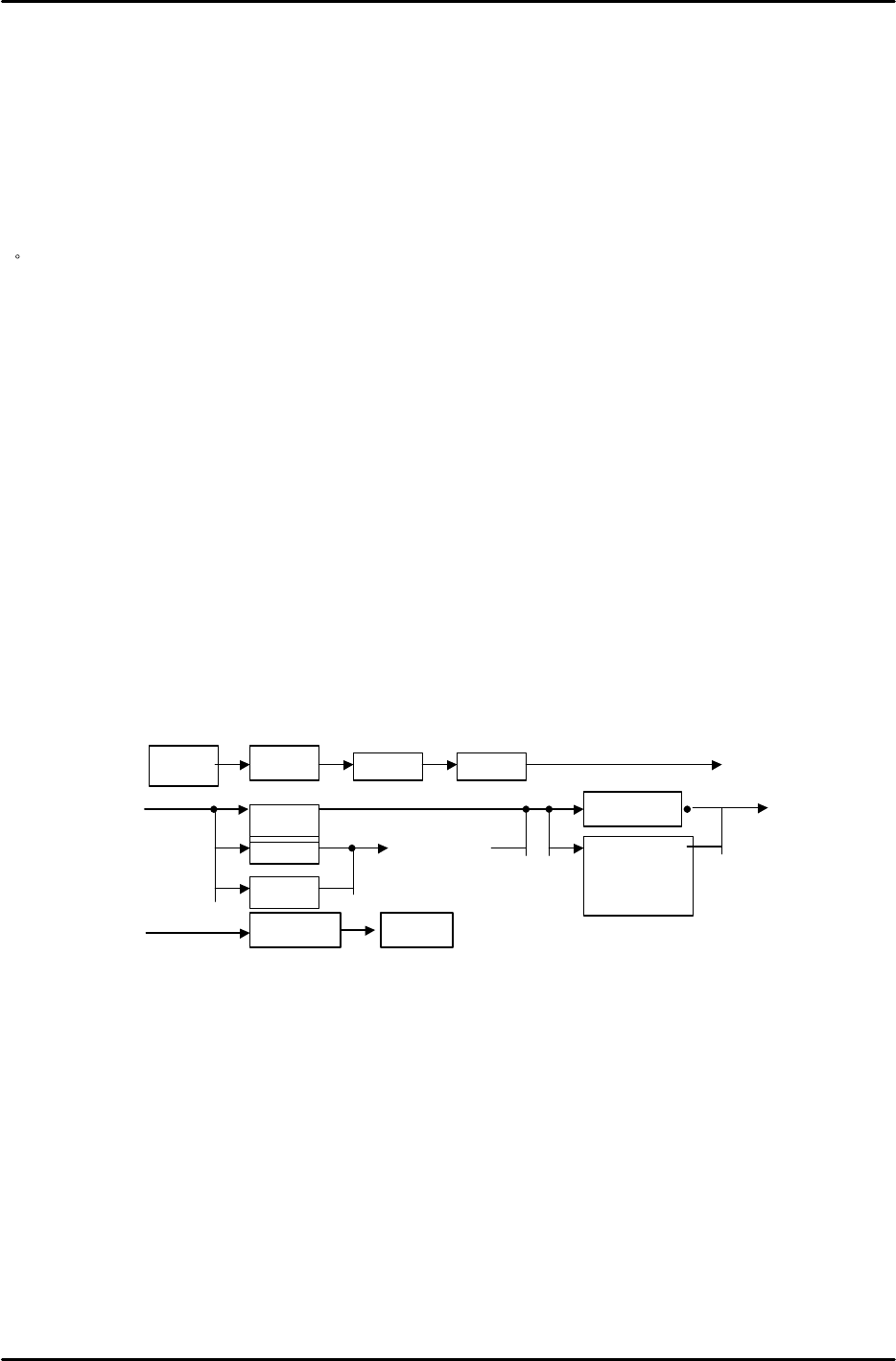
Set
ETC
Manua
l
Trace
I CM
SCU
PMC
Sel ect
modul e
Communi cati on
l og
Trace l i st
RS232COUT_PUT
A
A
B
B
FK-9F98-07 QP242E Training Text for Service Engineers
6th edition 15. Digital Amplifier Parameter Chart [1/4]
Fuji Machine Mfg. Co., Ltd. Okazaki
SMT Equipment Quality Assurance Dept.
Technical Support Div. Section No.2
15-1
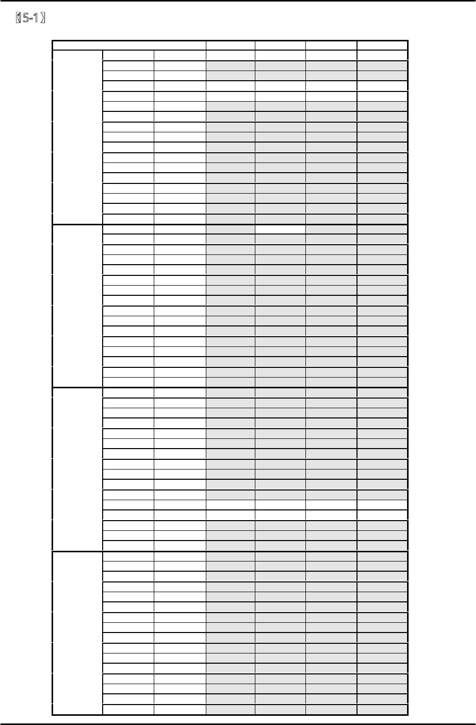
【15-1】
QP242E Digital amplifier parameter chart (Front device module)
Axis
SVA1
SVA2
SVA3
SVA4
Bit Default Y X Q Z
0 0 0 0 0 0
1 0 0 0 0 0
2 0 1 1 1 1
3 0 1 1 1 1
4 0 0 0 0 0
5 0 0 0 0 0
6 0 0 0 0 0
Cn−01 7 1 1 1 1 1
8 0 0 0 0 0
9 0 0 0 0 0
A 0 0 0 0 0
B 0 0 0 0 0
C 0 0 0 0 0
D 0 0 0 0 0
E 0 0 0 0 0
F 0 0 0 0 0
0
0
0
1
0
0
1 0 0 0 0 0
2 0 0 0 0 0
3 0 0 0 0 0
4 0 0 0 0 0
5 0 0 0 0 0
6 0 0 0 0 0
Cn−02 7 0 0 0 0 0
8 0 0 0 0 0
9 0 0 0 0 0
A 0 0 0 0 0
B 0 0 0 0 0
C 0 0 0 0 0
D 0 0 0 0 0
E 0 0 0 0 0
F 0 0 0 0 0
0
0
0
0
0
0
1 0 0 0 0 0
2 0 0 0 0 0
3 0 0 0 0 0
4 0 0 0 0 0
5 0 0 0 0 0
6 0 0 0 0 0
Cn−13 7 0 0 0 0 0
8 0 0 0 0 0
9 0 0 0 0 0
A 0 0 0 0 0
B 0 1 1 1 1
C 0 1 1 1 1
D 0 0 0 0 0
E 0 0 0 0 0
F 0 0 0 0 0
0 0 0 0 0 0
1 0 0 0 0 0
2 0 0 0 0 0
3 0 0 0 0 0
4 0 0 0 0 0
5 0 0 0 0 0
6 0 0 0 0 0
Cn−14 7 0 0 0 0 0
8 0 0 0 0 0
9 0 0 0 0 0
A 0 0 0 0 0
B 0 0 0 0 0
C 0 0 0 0 0
D 0 0 0 0 0
E 0 0 0 0 0
F 0 0 0 0 0
FK-9F98-07 QP242E Training Text for Service Engineers
6th edition 15. Digital Amplifier Parameter Chart [2/4]
Fuji Machine Mfg. Co., Ltd. Okazaki
SMT Equipment Quality Assurance Dept.
Technical Support Div. Section No.2
15-2
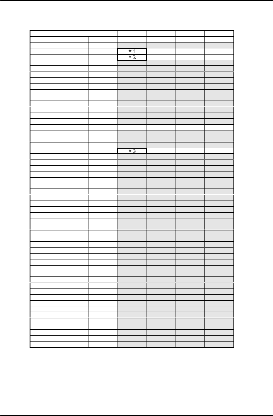
QP242E Digital amplifier parameter chart (Front device module)
Axis
SVA1
SVA2
SVA3
SVA4
Parameter No. Default Y X Q Z
*Cn−03 0 − − − −
Cn−04
400
*1
500
300
450
Cn−05 2000
*2
800 600 700
*Cn−06
max
−
−
−
−
*Cn−07 10 − − − −
Cn−08 max 316 300 310 317
Cn−09 max 316 300 310 317
Cn−0A 2048 2048 2048 2048 2048
*Cn−0B 0 − − − −
Cn−0C 200 200 200 200 200
Cn−0D 0 0 0 0 0
Cn−0E 0 0 0 0 0
Cn−0F 0 0 0 0 0
Cn−10 200 200 200 200 200
Cn−11 2048 4000 2000 2048 2048
Cn−12 0 0 0 0 0
Cn−15 100 100 100 100 100
Cn−16 50 50 50 50 50
Cn−17
400
*3
1000
500
600
Cn−18
0
0
0
0
0
Cn−19 0 0 0 0 0
*Cn−1A 4000 − − − −
*Cn−1B 7 − − − −
Cn−1C 0 0 0 0 0
*Cn−1D 0 − − − −
*Cn−1E 100000 − − − −
*Cn−1F 0 − − − −
*Cn−20 100 − − − −
*Cn−21 0 − − − −
Cn−22 50 50 50 50 50
Cn−23 5 5 5 5 5
*Cn−24 4 − − − −
*Cn−25 1 − − − −
*Cn−26 0 − − − −
Cn−27 0 0 0 0 0
Cn−28 100 100 100 100 100
Cn−29 0 0 0 0 0
Cn−2A 10 10 10 10 10
Cn−2B 100 100 100 100 100
Cn−2C 0 0 0 0 0
*Cn−2D 0 − − − −
*Cn−2E 0 − − − −
Cn−2F 57344 57344 57344 57344 57344
Cn−30 12499 12499 12499 12499 12499
Cn−31 57344 57344 57344 57344 57344
Cn−32 12499 12499 12499 12499 12499
Cn−33 0 0 0 0 0
Cn−34 0 0 0 0 0
Cn−35 0 0 0 0 0
Cn−36 0 0 0 0 0
Cn−37 0 0 0 0 0
*Cn−38 0 0 0 0 0
The section marked * will be transferred automatically from the machine during auto operation.
Values do not always match the default value in the chart.
*1 For 600mm modules: enter 500. For 800mm modules, enter 450.
*2 For 600mm modules, enter 1200. For 800mm modules, enter 1000.
*3 For 600mm modules, enter 2650. For 800mm modules, enter 2000.