QP-242E 工程师培训手册 (6.0).pdf.pdf - 第63页
FK-9F98-07 QP242E Training Text for Service Engineers 6th edition 7. Static Accuracy Measurement [ 1 / 6 ] Fuji Machine Mfg. Co., Ltd. Okazaki SMT Equipment Quality Assurance Dept. echnical Support Div. Section No.2 7- 1…

FK-9F98-07 QP242E Training Text for Service Engineers
6th edition 6. Proper Data Measurement [21/20]
Fuji Machine Mfg. Co., Ltd. Okazaki
SMT Equipment Quality Assurance Dept.
Technical Support Div. Section No.2
6-21
FK-9F98-07 QP242E Training Text for Service Engineers
6th edition 7. Static Accuracy Measurement [1/6]
Fuji Machine Mfg. Co., Ltd. Okazaki
SMT Equipment Quality Assurance Dept.
echnical Support Div. Section No.2
7-1
【Chapter 7】Operation and Function Check
[7-1]
Placement Accuracy Check
Glass boards and glass parts are expensive items. Please exercise caution in the
handling of these items during the course of this work.
Camera
type
Program name Parts Nozzle Board Measurement
1I
SEIDO_C1_M?_I
1S
SEIDO_C1_M?_S
3216PA
M chip
1.3 back light nozzle QP1/QP2 95-001
2I
SEIDO_C2_M?_I
2S
SEIDO_C2_M?_S
Glass
108pin
108pin glass board
3I
SEIDO_C3_M?_I
3S
SEIDO_C3_M?_S
Glass
132pin
132pin glass board
4, 7I
SEIDO_C4or7_M?_I
15.0 back light nozzle
4, 7S
SEIDO_C4or7_M?_S
Glass
284pin
20.0 back light nozzle
284pin glass board
DT-451
DT-651
6I
SEIDO_C6_M?_I
6S
SEIDO_C6_M?_S
Glass
60pin
7.0 back light nozzle 60pin glass board
Magnifying
glass
w/monitor
Note 1 : The "?" in the program name is the relevant module number (1 ~ 6).
Note 2 : Camera type "I" represents an index nozzle type and "S" represents a single nozzle type.
The number preceding the I or S indicates the camera type.
Note 3 : For camera type 4I, 4S, 6I, 6S, 7I, and 7S use a back light nozzle but carry out front light
processing.
Note 4 : A size 60 fluorescent seal must be affixed to the back light nozzle used with camera
type 2S, 3S, 4S, and 7S. (A 47 square fluorescent seal can be used as a substitute.)
Note 5 : Since the part data and nozzle data for the 20.0 back light nozzle used with camera
type 4S and 7S is processed using a nozzle size of 15.0, set the nozzle type item in nozzle
data to "129" so that nozzle check will not be performed.
Note 6 : The fluorescent seal used with camera type 2S, 3S, 4S, and 7S is larger than the nozzle
changer and as a result nozzle change should never be carried out.
1) Camera Type 1I and 1S
a) Install a 1.3 size back light nozzle on the relevant module.
b) Set a QP1/QP2 95-001 board (prepared with double-sided tape) on the ICM conveyor.
c) Transmit the placement program SEIDO_C1_M?_I or S to the machine.
d) Set a feeder loaded with 3216 Pam chips in the specified slot and enable automatic operation
to place the 3216 PAM chips.
e) Use the DT-451 (651) to carry out automatic accuracy measurement and then check the
placement accuracy.
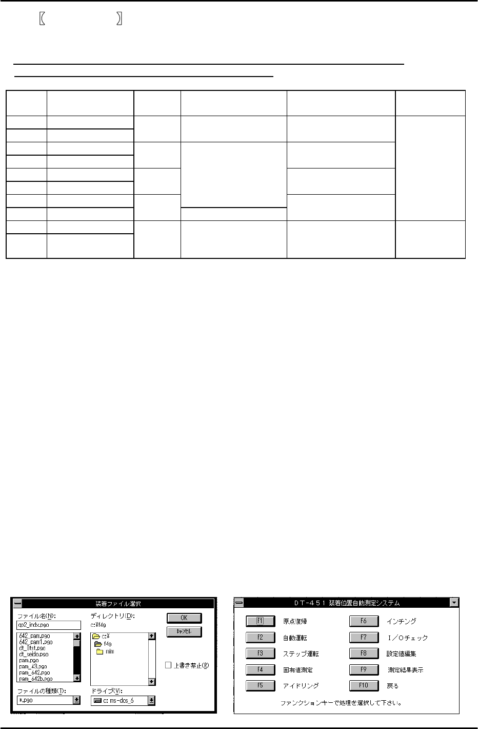
How to operate the DT-451 (651)
1) Set a QP1/QP2 95-001 board with 3216 PAM chip placement completed, in the board holder.
2) Click [F1] Origin on the computer operation display screen and wait for zero set to finish.
FK-9F98-07 QP242E Training Text for Service Engineers
6th edition 7. Static Accuracy Measurement [2/6]
Fuji Machine Mfg. Co., Ltd. Okazaki
SMT Equipment Quality Assurance Dept.
echnical Support Div. Section No.2
7-2
3) Click [F2] Auto, select "qp2_indx.pgo" from the placement file selection screen, and then
click [OK].
4) Press START once it begins flashing to start automatic measurement.
5) When automatic measurement finishes and the automatic measurement completion
screen displays, click [F1].
6) Enter a file name of eight characters or less and save the measurement data.
7) Double-click [Program Manager], [Accessory], and [Note Pad].
8) Open the relevant note pad file and then select [File] and [Print] to print the file.
f) Camera type 1I and 1S placement accuracy
Check whether the accuracy follows the specification.
Placement accuracy (3 sigma) à ± 0.1mm
Once the accuracy check is completed transmit the Proper data to F4G and then save the
data.
g) If the placement accuracy results exceed the allowable tolerance ranges then carry out
calibration (Center_Offset, Final_Offset).
Center_Offset is the compensation value for offsetting the nozzle center of rotation to zero.
Final_Offset is the compensation value for offsetting the average value of all placement
parts to zero.
h) Add the Center_Offset X and Y and Final_Offset X and Y values to the original value and
then directly enter the values at the machine using the following command operation.
[PROPER], [CAMERA], [ETC], [ETC], select [Center_Offset] or [Final_Offset] for input, use
the arrow keys to select X or Y, input the value and then hit return.
<<How to obtain the input value>>
As shown in the figure to the right, a total of 32 parts (3216 PAM chips) are placed.
Center_Offset X and Y are obtained using the following equation.
(0 degree’s average value – 180 degrees average value) ÷ 2
Final_Offset X and Y are obtained from the average value of all placed parts.
Obtain the sign of the input offset values for Center_Offset X and Y and Final_Offset X and Y from
the following table.
0degrees
90degrees
270degrees
180degrees
QP1/QP2 95-001 board