QP-242E 工程师培训手册 (6.0).pdf.pdf - 第29页
FK-9F98-07 QP242E Training Text for Service Engineers 6th edition 3. QP242E Initial Adjustment (2) [ 12 /12] Fuji Machine Mfg. Co., Ltd. Okazaki SMT Equipment Quality Assurance Dept. Technical Support Div. Section No.2 3…
FK-9F98-07 QP242E Training Text for Service Engineers
6th edition 3. QP242E Initial Adjustment (2) [11/12]
Fuji Machine Mfg. Co., Ltd. Okazaki
SMT Equipment Quality Assurance Dept.
Technical Support Div. Section No.2
3-11
0.1mm
0.05mm
Sensor on
detection height
MFU guide's
top face
Sensor off
confirmation height
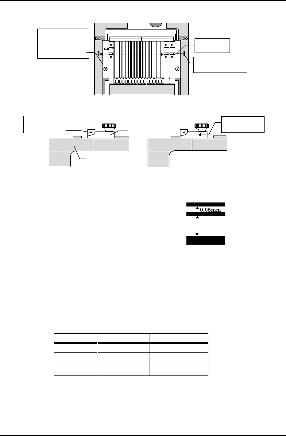
[3-15] MFU Set Sensor Adjustment
Adjust the sensor height so that the sensor switches from on to off at a point 0.10mm above the
top face of the MFU guide. Verify that the sensor
definitely switches off at 0.15mm above the MFU guide.
1) Adjust the sensor mounting bracket so that it is flat
(within 0.10mm at both ends).
2) Set a jig so that its detection face is 0.10mm above the
MFU rail's top face, then adjust the sensor height to the
position where the sensor switches from on to off.
3) Set a jig so that its detection face is 0.10mm above the MFU
rail's top face and verify that the sensor is off.
4) Set a jig against the MFU rail's top face and verify that the sensor is on.
5) Set an actual MFU at the machine and verify that the sensor operates normally. Be sure to
confirm this at the I/O screen (X014 MFU, MTU CONECT). At old type main relay boards, the
sensor lamp comes on but the I/O input does not occur. Also be sure that the MFU cable (or
dummy connector) is connected to the QP242 (this is because the "MFU Set" and "cable
connection" confirmations are serial I/O commands.)
* Note: There is an old type MFU (with a black steel bracket on the MFU's mounting face,
extending to the rear), and the current type MFU. The adjustment values are different
for these two types, as shown below.
★
Sensor beam
position
Slit
★
Move slit to
check
Device jig
Sensor on Sensor off
1 2119
Bar jig
(1.8mm dia.)
Align jig with center
of sensor beam
Move jig from
D19 to D1 and
align with sensor
beam
MFU
Camera
MFU Type Detection Height Check Height
Current type 0.10mm 0.15mm
Mixed types 0.15mm 0.20mm
Old (original)
type
0.15mm 0.20mm
FK-9F98-07 QP242E Training Text for Service Engineers
6th edition 3. QP242E Initial Adjustment (2) [12/12]
Fuji Machine Mfg. Co., Ltd. Okazaki
SMT Equipment Quality Assurance Dept.
Technical Support Div. Section No.2
3-12
[3-16] Nozzle Changer Operation Check and Sensor Adjustment (For Single Types Only)
1) Changer UP/DOWN operation check
Use the following commands to raise and lower the changer unit:
[SET]è[POSITION]è[MODULE NO.]è [NOZZLE]è[STATION]è[UP][DOWN].
Verify that the changer operates in a smooth manner.
2) Shutter operation check
1. Open and close the shutter by turning the "X020 NZL SHTTR CLS" and "X021 NZL
SHTTR OPEN" I/O commands on and off. Verify that the shutter opens and closes in a
smooth manner.
2. At the shutter open position, align the center of the shutter hole with the center of the
station nozzle holder hole. This is done by turning the adjusting bolt, and by adjusting
the shutter open/close cylinder stroke.
3. Adjust the shutter OPEN/CLOSE limit sensors. With the shutter open, move the shutter
OPEN sensor downward until it switches off. Next, raise the sensor to the point where it
switches on again, then secure the sensor 0.5mm below that point. Move the shutter
CLOSE sensor upward until it is against the top bracket (it cannot be raised higher than
this), then secure it 0.5mm below that position.
Release the air from the shutter OPEN/CLOSE cylinder and move the shutter by hand,
verifying that the shutter OPEN/CLOSE sensors remain on through a distance of 0.5mm
(at the cylinder stroke). If they do not remain on through a distance of 0.5mm, adjust the
sensor positions (up and down) until the distance is 0.5mm.
4. After completing the adjustments, open and close the shutter again, verifying that the
inputs occur at the I/O IN side. Also verify that the sensor switches off when a nozzle is
clamped (for nozzle clamp detection function).
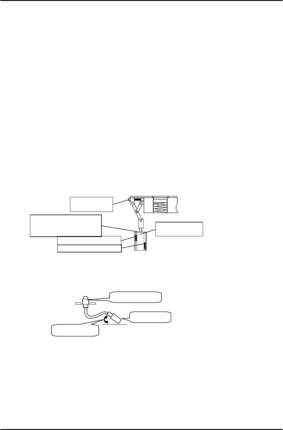
[3-17] Securing the Head's Vacuum Hose
Secure the head's vacuum hose as shown below with the ejector elbow facing inward (to
prevent hose interference).
Ball-
spline elbow
Ejector elbow
Facing inward
Shutter CLOSE sensor
Shutter OPEN sensor
Nozzle changer
shutter
adj ust i ng bol t
Shutter
OPEN/CLOSE
cylinder
Shutter CLOSE sensor
cannot be raised higher
than this BKT.
FK-9F98-07 QP242E Training Text for Service Engineers
6th edition 4. Axis Zero Setting Adjustment [1/6]
Fuji Machine Mfg. Co., Ltd. Okazaki
SMT Equipment Quality Assurance Dept.
Technical Support Div. Section No.2
4-1
[Chapter 4] Axis Zero Setting Adjustment
[Explanation of Chapter 4]
This chapter describes the axis zero setting adjustment procedure which is performed at the
standard display screen. Be sure to verify that zero settings have been specified before
attempting this adjustment procedure. The "mechanical check" mode zero setting
adjustment procedure is described at the end of this chapter. Select the procedure which is
appropriate.
X axis 0.0025mm / Pls
Y axis 0.0025mm / Pls
Z axis 0.0015mm / Pls
Q axis 0.005degrees / Pls
[4-1] Cooling Fan Operation Check
Verify that all cooling fans are operating when the PLM starts up at power on.
[4-2] Digital Amplifier Parameter Check
Connect a digital operator to "ch3" of the amplifier being checked,
and verify that all settings are correct.
[Using the digital operator]
1) Connect the digital operator to each servo amplifier.
Either "[-.bb]" (100V) or "[run]" (200V) displays at this time.
2) Execute the following sequence to verify that the "CN-00" parameter is "00-00":
[–.bb [–.bb] à DSPL à Cn-00 à DATA
SET ENTER
3) Execute the following sequence to verify the "CN-01" parameter:
DSPL à Cn-00 à à Cn-01à DATA
SET ENTER
* Reverse the above sequence to return to the original display.
[4-3] Temporary Zero Setting
Adjust until a zero setting is possible.
Press the [START] button to end the zero setting procedure.
Note: If the zero setting cannot be ended, adjust each axis using the mechanical check mode
zero setting procedure described in section [4-2].
[4-4] Before Beginning the Axis Zero Setting Adjustments
1) If an index holder or a single nozzle holder is mounted at the head, be sure to remove the
holder to prevent interference with the table and brackets.
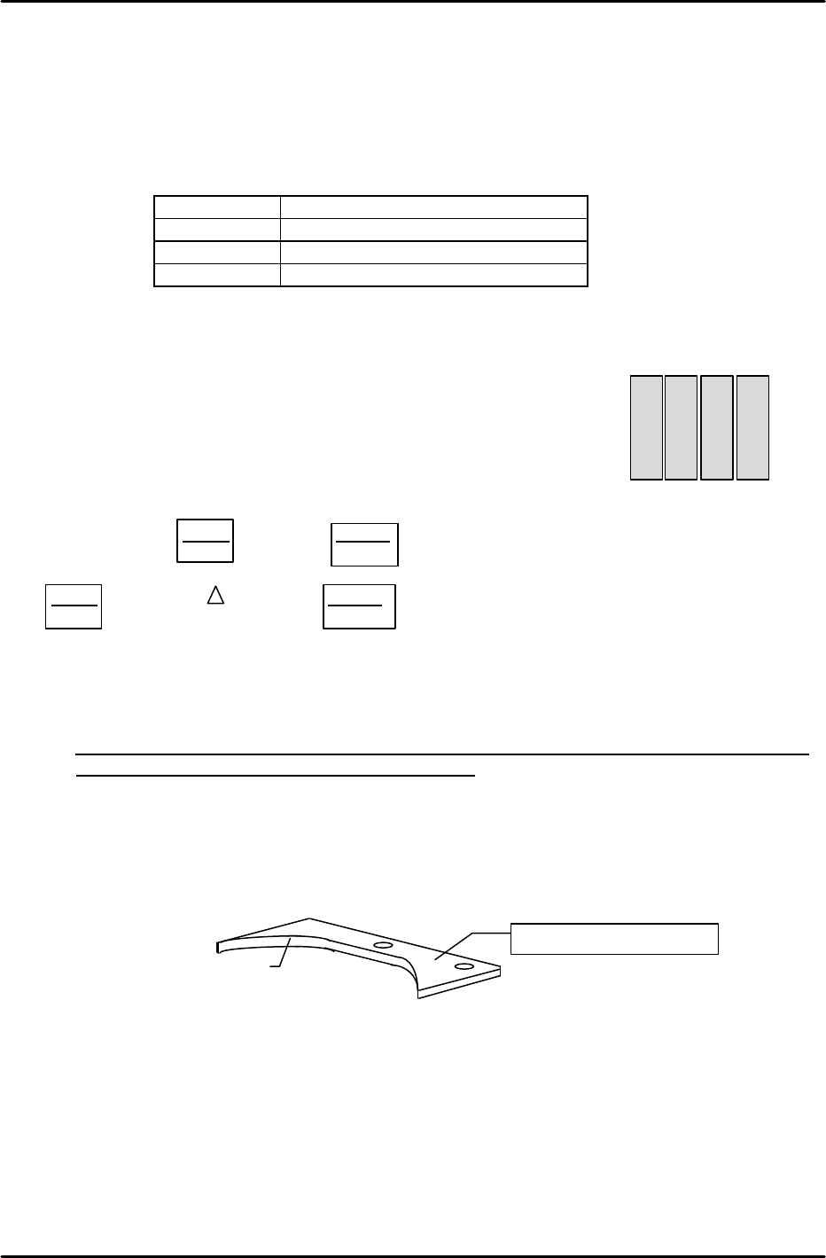
2) If an index head is being used, remove the nozzle changer holder's bracket. Do not remount
this bracket until just before the Proper data measurement is performed.
3) Press the Emergency Stop button to turn off the 200V power supply.
4) Execute the following on-screen command sequence to display the servo counter screen for
the module to be adjusted: [SET]->[SERVO]->[Number of module to be adjusted]->[CR]
5) Remove the X-axis timing belt, the Y-axis coupling, and the Z-axis timing belt, then adjust
each axis as described in the following sections.
Nozzle changer bracket
Nozzle changer grounding face
SAV1
SAV2
SAV3
SAV4
X
Y
Q
Z