QP-242E 工程师培训手册 (6.0).pdf.pdf - 第104页
FK-9F98-07 QP242E Training Text for Service Engineers 6th edition 13. MTU 71E Adjustment [ 2 /24] Fuji Machine Mfg. Co., Ltd. Okazaki SMT Equipment Quality Assurance Dept. Technical Support Div. Section No.2 13- 2 [ 1 3 …
FK-9F98-07 QP242E Training Text for Service Engineers
6th edition 13. MTU 71E Adjustment [1/24]
Fuji Machine Mfg. Co., Ltd. Okazaki
SMT Equipment Quality Assurance Dept.
Technical Support Div. Section No.2
13-1
[Chapter 13] MTU71E Adjustment
Note: If the by-pass key is inserted in the mechanical switch of the MFU
specifications safety door, remove the key and put it in the MTU cover.
If the key is left inserted in the MFU specifications switch this will disable
the MTU front safety door by-pass key which can lead to damage.
[13-1] Prior to Adjusting the MTU71E
- Since layered stacking of trays is possible on the MTU71E, an additional 10 to 20 part types can be
loaded on the MTU71E compared to the MTU6 (MTU6 can handle 50 to 100 types of parts).
- There is a detachable type tray remover on the changer unit that is needed for removing empty trays.
By attaching this to the placing head, empty trays can be removed in conjunction with the layered tray
stacking specifications.
- On modules that utilize an MTU71E it is possible to change from an MTU71E to an MFU. However,
when installing an MTU71E on an MFU module, additional work related to the shuttle, remover
station and Proper data measurement are required.
- When connecting the MTU71E unit to the machine, the machine should be zero set and the 100 V
power should be on before connecting the MTU71E. If zero setting is performed after connecting the
unit to the machine there is a danger of damage being caused by a collision between the shuttle jaw and
the tray holder. For details refer to the material from what to do prior to connecting the MTU up to the
measurement of Orgn. Pos. TY.
- When the MTU71E is removed from the machine always verify that the shuttle jaw and tray holder are
separated and that the shuttle jaw has been advanced forward before carrying out the removal work.
The shuttle may be damaged if the jaw is at the retract limit.
- On modules with an MTU71E installed, the maximum part size that can be loaded is 50 mm square.
This is because the width of the reject parts conveyor is 54 mm (the 4 mm difference is to take part
pickup deviation ± 2 mm into account).
- MTU71E Specifications
Suitable machine : QP-242 600 type and 760 type
Number of part types that can be loaded : 10 types/Unit (Large parts tray), 20
types/Unit (Small parts tray)
Tray stacking height : 32 mm/level
Tray size : 335 x 250 mm (1part type/level), 130 x 250 mm
(2 part types/level)
Maximum load weight per tray pallet : 2.0 Kg
Permissible empty tray load weight : 240 g/tray
Minimum tray thickness : 4 mm
Empty tray removal speed : Within 8 seconds
Special air source required for MTU71 (for remover)
TY-axis : 0.09 mm/Pulse
TZ-axis : 0.01 mm/Pulse
Required number of magnets : New model 60, existing model 20 for total of 80
magnets/MTU
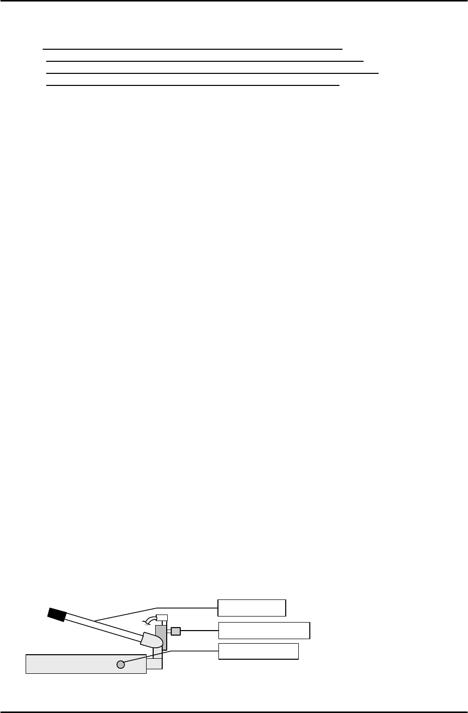
[13-2] MTU Descent Speed Adjustment
Raise the MTU by the maximum stroke using the hydraulic jack then use the speed controller
beside the jack to adjust the speed so that the operation time from the opening of the hydraulic jack
valve to the end of descent is between 6 and 10 seconds.
Speed controller
Descent valve
Ascent lever
FK-9F98-07 QP242E Training Text for Service Engineers
6th edition 13. MTU 71E Adjustment [2/24]
Fuji Machine Mfg. Co., Ltd. Okazaki
SMT Equipment Quality Assurance Dept.
Technical Support Div. Section No.2
13-2
[
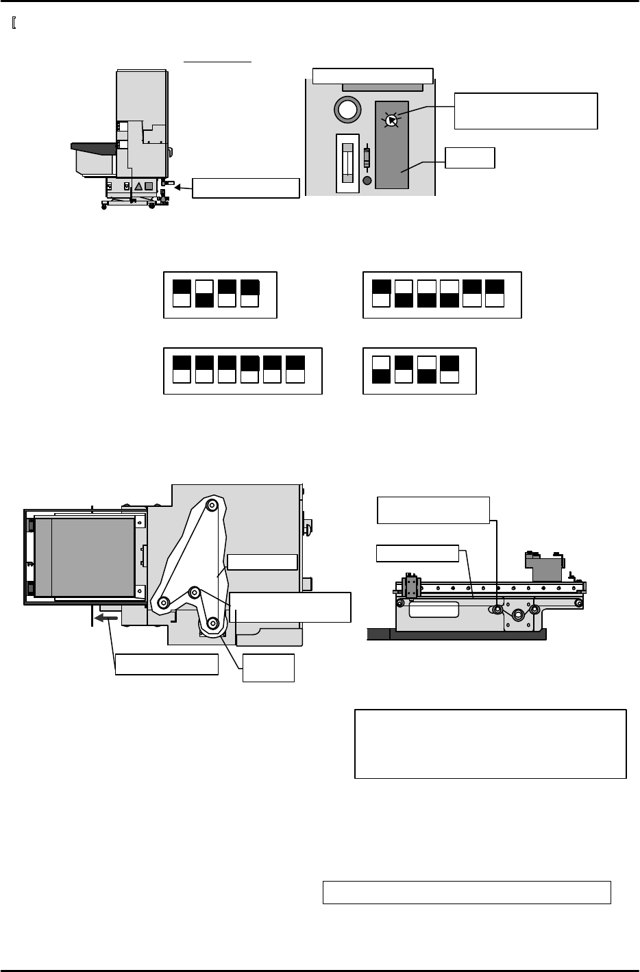
13-3] Timer Adjustment
Remove the cover from the control box on the bottom of the MTU71E and set the timer located on
the left side relay board to 0.4 seconds.
[13-4] Servo Amp Dip Switch Settings
Set the dip switches on each servo amp as shown in the figures below.
[13-5] TZ-axis and TY-axis Timing Belt Removal
1) Open the safety door on the MTU7 and loosen the belt tension adjustment pulley.
2) Remove the side cover below the empty tray removal box and remove the TZ-axis timing belt.
3) Loosen the shuttle assembly belt tension adjustment pulley and remove the TY-axis timing belt.
[13-6] Shuttle Assembly Preliminary Installment
1) Insert the MFU set rail side positioning pin on
the nozzle change unit side of the machine into
the shuttle assembly and provisionally secure
the shuttle assembly in place.
2) After provisionally securing the shuttle assembly,
connect the power cable.
[13-7] Remover Station Installation
Install the remover station on the machine base and secure in place such that the side of the base
and side of the installation bracket are roughly parallel. The bolts can be easily attached if the
remover station is raised.
M6 x 15: Cap bolt and spring washer 2 each
M6 x 20: Cap bolt and spring washer 3 each
M5 x 20: Cap bolt and spring washer 1 each
M5 x 10: Cap bolt and spring washer 1 each
Control box cover
OMRON H3FA-A
L
S
Timer
Second mark from S on
the scale = 0.4 seconds
Intermediate board
Belt tension
adjustment pulley
Timing belt
View from the
top of MTU7
Remove the cover
TZ-axis
motor
Belt tension
adjustment pulley
Timing belt
View from the interior
side of the shuttle
1 2 3 4
àNO
3SA1
SW
1 2 3 4 5 6
àNO
3SA2
(Left side of amp)
1 2 3 4
1 2 3 4 5 6
àNO
àNO
No.1EV CONT
SW2
No.1EV CONT SW1
FK-9F98-07 QP242E Training Text for Service Engineers
6th edition 13. MTU 71E Adjustment [3/24]
Fuji Machine Mfg. Co., Ltd. Okazaki
SMT Equipment Quality Assurance Dept.
Technical Support Div. Section No.2
13-3
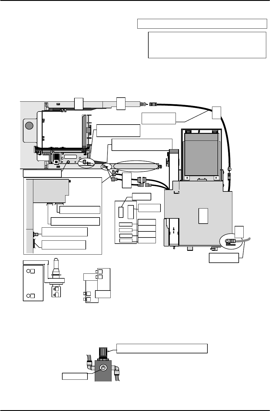
[13-8]
MTU71E Unit Preliminary Connection
1) In the position where the MFU safety door
acrylic cover is usually installed, instead
install the remover relay box.
2) Attach the relay terminals to the machine
base and after connecting the wiring and
tubing then install the wiring and tubing cover.
3) Since zero set adjustment cannot be carried out if the MTU71E is joined to the machine,
provisionally position the unit away from the machine in either the front or rear where
adjustment can be performed. Then temporarily connect the unit to the machine using the
power extension cable for adjustment.
4) Connect the air supply and open the pneumatic valve to supply air to the unit.
[13-9] Air Regulator Adjustment
After air pressure is supplied to the unit, turn the air regulator cock until the pressure gauge
registers 0.5 Mpa.
Mpa
Turn the cock to adjust the pressure.
MTU inner right side position
0.5Mpa
M4 x 8: Cap bolt and spring washer 2 each
M3 x 8: Round screw and spring washer 2 each
M4 x 10: Cap bolt and spring washer 1 each
Air hose
M/C
Camera
Connect the cable from
the MTU
MTU power cable
MTU I/O
cable
MFU I/O
cable
Error
conv.
I/O
cable
M/C
Intermediate
air hose
4
Front
fence
3
5
3
1
2
Connect the cable
from the shuttle
Positioning pin
1
2
3
1
2
4
4
3
Remover solenoids
Remover cylinder
Locations at which the number seals should be affixed to denote the tubing positions.
CJ5A
CJ6A
CJ4A
CJ7A
CJ8A
Relay terminals ②
CNP33A
M6 x 15: Hexagonal bolt and spring washer 2 each