QP-242E 工程师培训手册 (6.0).pdf.pdf - 第16页
FK-9F98-07 QP242E Training Text for Service Engineers 6th edition 2. Static Accuracy Measurement [ 1 / 2 ] Fuji Machine Mfg. Co., Ltd. Okazaki SMT Equipment Quality Assurance Dept. Technical Support Div. Section No.2 2- …

FK-9F98-07 QP242E Training Text for Service Engineers
6th edition 1. QP242E Initial Adjustment (1) [6/
6
]
Fuji Machine Mfg. Co., Ltd. Okazaki
SMT Equipment Quality Assurance Dept.
Technical Support Div. Section No.2
1-
6
***** This page does not contain any contents.
FK-9F98-07 QP242E Training Text for Service Engineers
6th edition 2. Static Accuracy Measurement [1/2]
Fuji Machine Mfg. Co., Ltd. Okazaki
SMT Equipment Quality Assurance Dept.
Technical Support Div. Section No.2
2-1
[Chapter 2] Static Accuracy Measurement
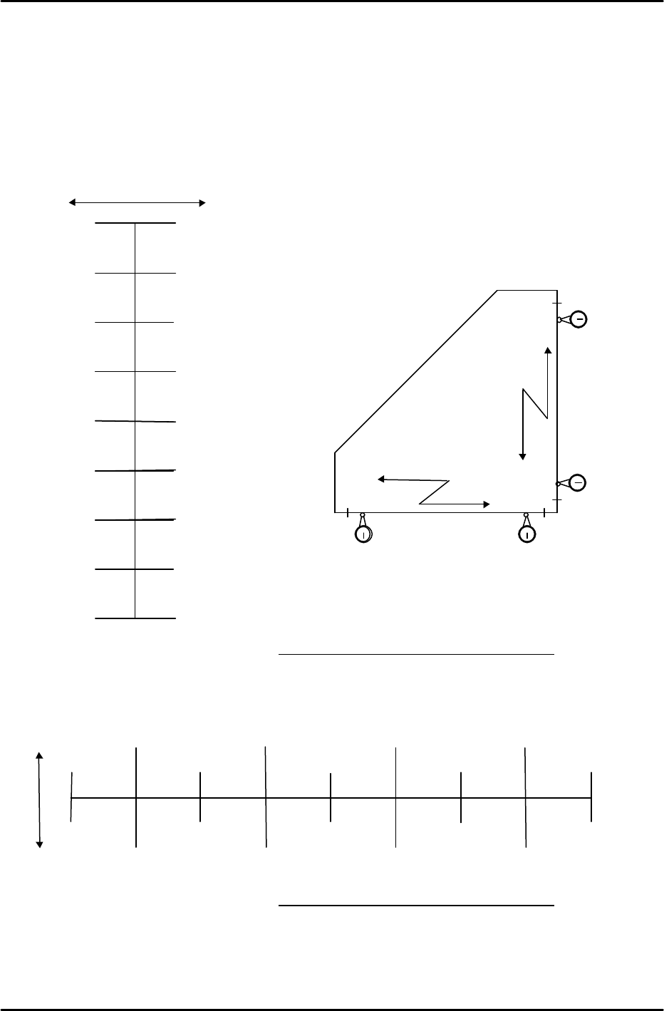
[2-1] X, Y Axes Straightness Measurement
1) Place a right-angled jig on the conveyor in a position that is parallel (approximately) with the X and Y
axes.
2) Mount a dial gauge holder shaft on the end of the placing head, then measure the Y-axis straightness
while moving the head by hand in the Y-direction.
Y-axis movement distance (mm)
Tolerance: 0.03 / 400 (mm) Y-measurement value: / 400 (mm)
3) Measure the X-axis straightness while moving the head by hand in the X-direction.
Tolerance: 0.03 / 400 (mm) X-measurement value: / 400 (mm)
150
50
250
0
100
200
300
350
–
+
X-axis movement distance (mm)
400
0
0
0
0
0
X direction
0
50
100
150
200
250
300
350
+ –
400
0
( )
( )
( )
( )
( )
( )
( )
0
Y direction
0
( )
( )
( ) ( ) ( )
( ) ( )
FK-9F98-07 QP242E Training Text for Service Engineers
6th edition 2. Static Accuracy Measurement [2/2]
Fuji Machine Mfg. Co., Ltd. Okazaki
SMT Equipment Quality Assurance Dept.
Technical Support Div. Section No.2
2-2
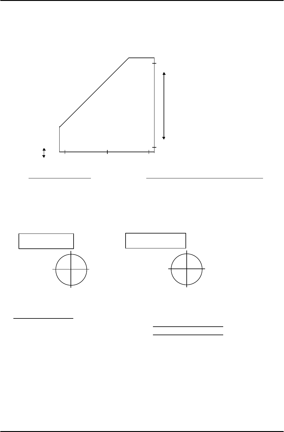
[2-2] X, Y Axes Squareness Measurement
1)Place a right-angled jig on the conveyor and use a dial gauge to position one of the jig's sides so that it is
parallel with the Y-axis.
2)While maintaining this jig position, measure the other side in the X-direction. The amount of X-axis
tilt indicates its straightness relative to the Y-axis.
Tolerance: 0.03 / 400mm Measurement value: / 400 (mm)
[2-3] Z-axis Perpendicularity Measurement
1) Mount a dial gauge on the end of the spline axis, then set a cylindrical jig on the base.
2) With the cylindrical jig's top positioned approximately 5mm below the Z-axis UP limit mechanical
stopper, measure the amount of swing. Next, position the jig's bottom so that it is 30mm lower than
the above position and repeat the swing amount measurement.
Tolerance: 0.03 / 30mm
Difference between jig top/bottom measurements: X (mm)
Y (mm)
Y-direction
( )
Y-direction
( )
X-direction
( )
X-direction
( )
Jig top measurement
Y-direction
( )
Y-direction
( )
X-direction
( )
X-direction
( )
Jig bottom measurement
( ) ( )
0
0
0
400mm
–
+
0