QP-242E 工程师培训手册 (6.0).pdf.pdf - 第119页
FK-9F98-07 QP242E Training Text for Service Engineers 6th edition 13. MTU 71E Adjustment [ 17 /24] Fuji Machine Mfg. Co., Ltd. Okazaki SMT Equipment Quality Assurance Dept. Technical Support Div. Section No.2 13- 17 via …
FK-9F98-07 QP242E Training Text for Service Engineers
6th edition 13. MTU 71E Adjustment [16/24]
Fuji Machine Mfg. Co., Ltd. Okazaki
SMT Equipment Quality Assurance Dept.
Technical Support Div. Section No.2
13-16
[
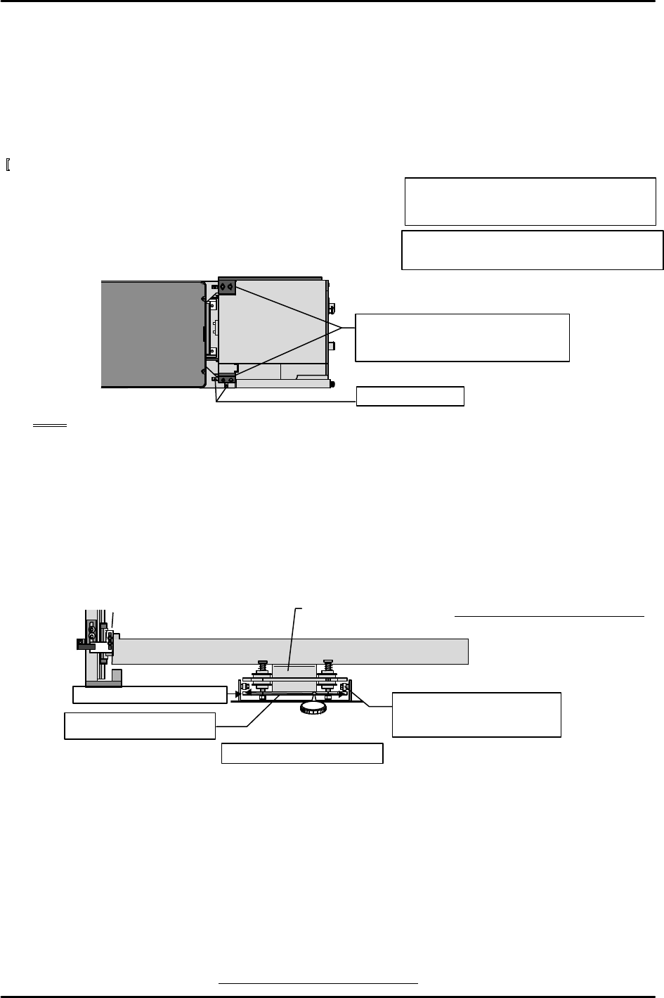
13-45] Securing the MTU71E in place
1) Attach the guide brackets on the left and right side
of the top of the MTU7 unit and secure the unit to the
machine side.
2) After securing the guide brackets in place, secure the
positioning blocks touching the sides of the brackets
as shown in the figure below.
Note: Carefully install the guide brackets so that the MTU71E cannot twist or turn.
[13-46 ] Shuttle Jaw Installation Position Adjustment and Left to Right Angle Adjustment
1) Adjust the shuttle jaw bracket installation position so that the two guide rollers on the end
of the tray holder plate are positioned equally in relation to the left and right end of the
shuttle jaw.
2) Use the dial gauge to measure the top of the stationary side claw in the X-direction and
adjust the shuttle jaw bracket angle such that difference between ends is within tolerance.
Once adjustment is completed verify that the guide roller positions remain equally
positioned.
[13-47 ] Original_Position_TY
1) Remove the blue duracon tray pusher from the shuttle.
2) There are two stoppers for adjusting the shuttle jaw opening amount that are installed in
the vicinity of the guide rollers of the stored tray holder plate. The stopper length should
be left about 10 mm from the mounting surface. The nut does not have to be tightened.
3) Move the TY-axis to a position where the guide rollers attached to the tray holder
mechanism are able to easily pass through the inside of the shuttle jaw (jaw opening is
about 10 mm). Check that nothing is causing interference and then slowly raise the TZ-axis
M8X30: cap screw
Lock washer, and W4 flat washer 8 each
M/C
MTU7
Secure the brackets with each side of
the bracket making contact such that
the unit cannot twist or turn.
Positioning block
M6X20: cap screw
Lock washer, and 4W flat washer 3 each
Shuttle bar
Shuttle jaw stationary side
( 0 ) ( )
Tolerance : within
±
0.2mm
Measure the top surface
in the X-direction
Shuttle jaw bracket
21
Check that both rollers are
equally positioned from the
end of the jaw.
Tolerance: Within +/- 0.2 mm
FK-9F98-07 QP242E Training Text for Service Engineers
6th edition 13. MTU 71E Adjustment [17/24]
Fuji Machine Mfg. Co., Ltd. Okazaki
SMT Equipment Quality Assurance Dept.
Technical Support Div. Section No.2
13-17
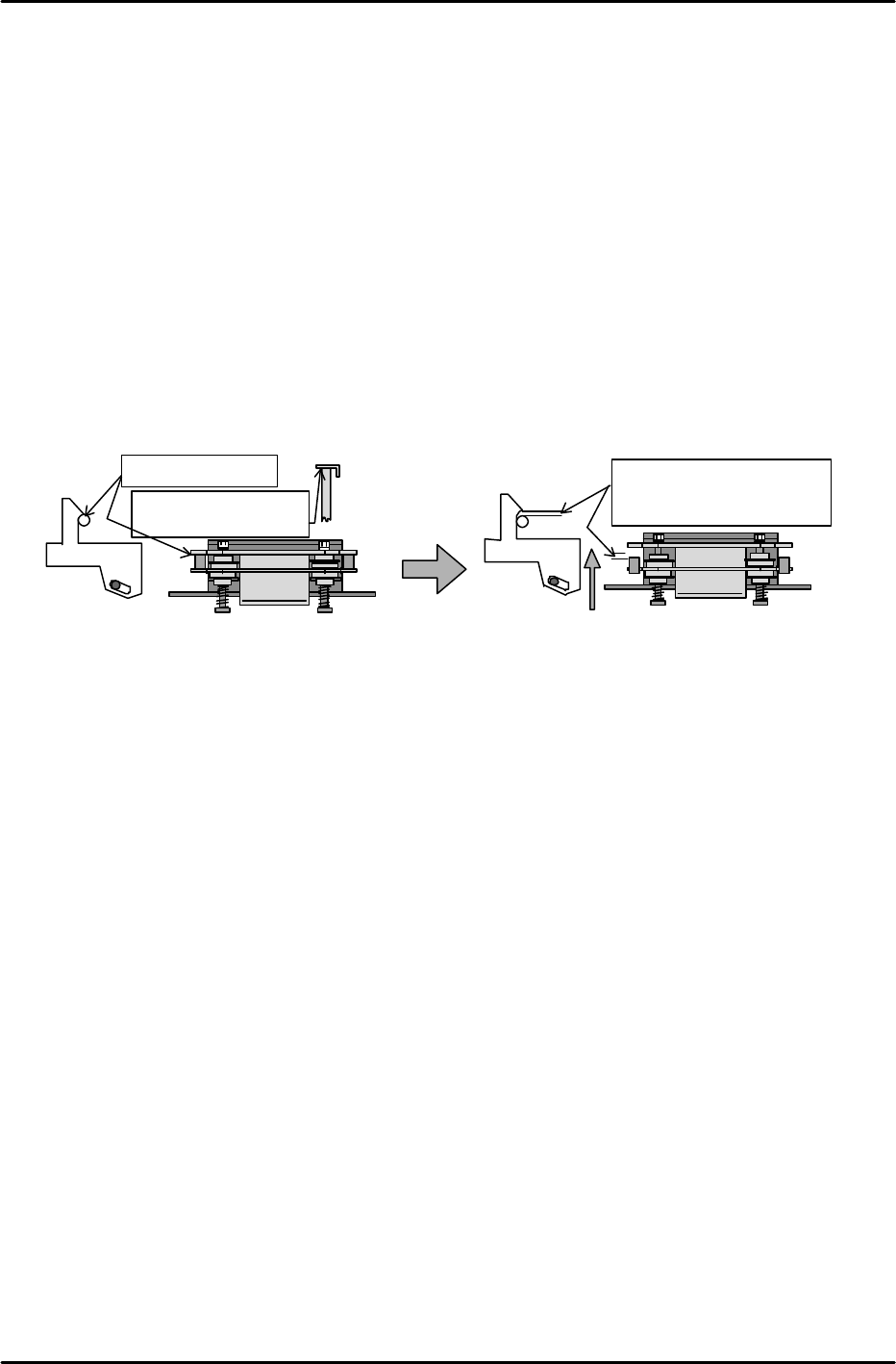
via inching to the Original_Position_TZ position.
4) With the tray holder in the clamped status, move the TY-axis to the forward limit.
5) Since a gap can be created between the discharged tray holder plate and the MTU71E,
loosen and remove both of the stoppers that were temporarily adjusted earlier.
6) Loosen the cam jaw mount on the bottom of the shuttle jaw mechanism and retract the TY-
axis again via inching. At this point, stop the TZ-axis in a position where the end of the LM
guide rail on the returned tray holder plate skims the guide on the safety door, and where
there is no space between the curved portion of the cam jaw and the cam rollers (since the
cam jaw remains loosened at this time, the position on the LM guide side should be given
precedence).
7) In this position, adjust the position of the loosened cam jaw so that the curved surface on
both the left and right side of the cam jaw catches the cam rollers.
8) From the position at which the above conditions are satisfied, retract the TY-axis another 10
pulses. This becomes Original_Position_TY. Use the following command operation on the
operation panel to enter the value automatically: [PROPER], [DEVICE], [ORG.POS.TY],
and [SET].
Contact status
Pushed in 10 pulses (1 mm)
Original_Position_TY
Cam jaw
Cam jaw
Move the TY-axis via inching
LM guide rail should
make contact with the
guide
Safety Door Side
FK-9F98-07 QP242E Training Text for Service Engineers
6th edition 13. MTU 71E Adjustment [18/24]
Fuji Machine Mfg. Co., Ltd. Okazaki
SMT Equipment Quality Assurance Dept.
Technical Support Div. Section No.2
13-18
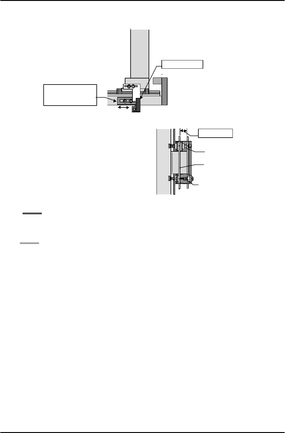
[13-48] TY-axis Retract Limit (Escape Position) Sensor Adjustment
At the Original_Position_TY position adjust the sensor mounting bracket position so that the
end surface of the dog and sensor are aligned along the same plane.
[13-49 ] Shuttle Jaw Opening Adjustment
1) Move the TY-axis to the forward limit and
return the jaw opening adjustment stoppers
that were removed earlier to their original
positions. Align so that the length of the
stoppers is approximately 10mm.
2) Move the TY-axis back to the
Original_Position_TY position again. Adjust
the length of the stoppers and open the
moveable claw of the jaw to a position where
the gap between the inside of the stationary
claw and the outside of the moveable claw is between 9.5 and 10.5 mm.
NOTE: Carefully adjust the balance of both stoppers.
3) Verify that the dog does not separate from the retract limit sensor as a result of the spring
force of the shuttle jaw even when the emergency stop status is activated at the
Original_Position_TY position.
NOTE: If the TY-axis moves away from the retract limit sensor as a result of an emergency
stop it is possible that the cam jaw contact is weak. However, care should be
exercised since if the contact is too strong this will increase the friction when a tray
is stored and lead to tray vibration.
4) Once adjustment is completed verify that there is no interference when the TZ-axis is moved
up and down at the Original_Position_TY position.
Shuttle
bar
Original_Position_TY position
Same plane
Move the sensor
bracket to adjust
Shuttle bar
10 mm gap
Adjust the stopper bolt at the
Original,TY posiiton
Shuttle jaw stationary side
Shuttle jaw secondary side