QP-242E 工程师培训手册 (6.0).pdf.pdf - 第68页
FK-9F98-07 QP242E Training Text for Service Engineers 6th edition 7. Static Accuracy Measurement [ 6 / 6 ] Fuji Machine Mfg. Co., Ltd. Okazaki SMT Equipment Quality Assurance Dept. echnical Support Div. Section No.2 7- 6…
FK-9F98-07 QP242E Training Text for Service Engineers
6th edition 7. Static Accuracy Measurement [5/6]
Fuji Machine Mfg. Co., Ltd. Okazaki
SMT Equipment Quality Assurance Dept.
echnical Support Div. Section No.2
7-5
g) If the placement accuracy results exceed the allowable tolerance ranges then carry out
calibration (Center_Offset, Final_Offset).
h) Add the Center_Offset X and Y and Final_Offset X and Y values to the original value and
then directly enter the values at the machine using the following command operation.
[PROPER], [CAMERA], [ETC], [ETC], select [Center_Offset] or [Final_Offset] for input, use
the arrow keys to select X or Y, input the value and then hit return.
<<How to obtain the input values>>
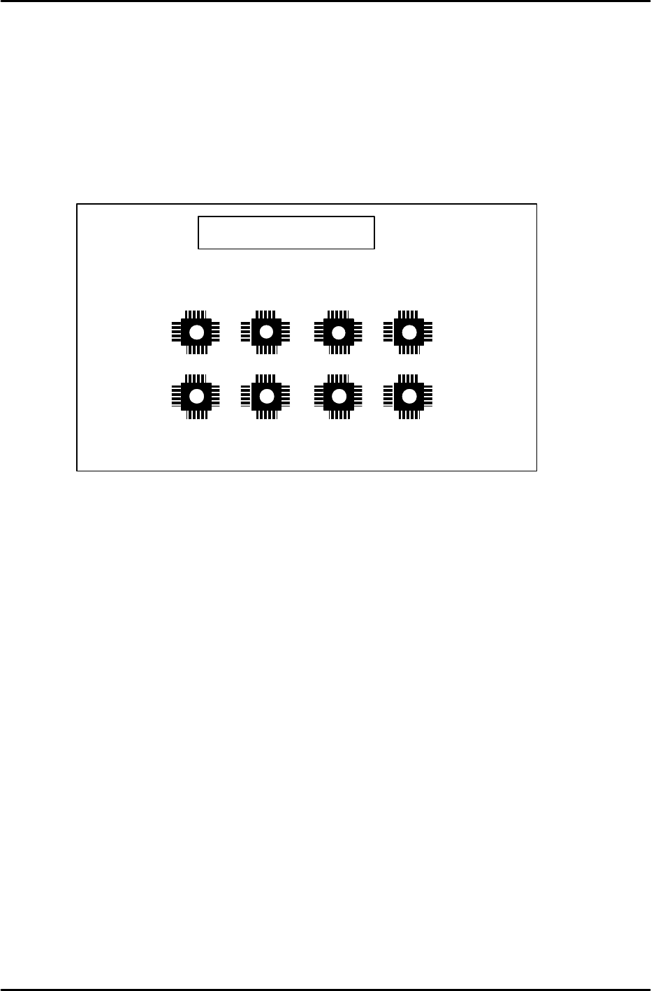
A total of eight 60-pin glass parts are placed as shown in the figure above.
The glass board and parts form a vernier scale (1 graduation is 0.005 mm).
Measure how many graduations the conforming location (location where the 4 leaded
sides of a part match the pattern) deviates from the pattern center.
Center_Offset X and Y are obtained by (0 degree’s value – 180degrees’ value) / 2.
Final_Offset X and Y are obtained from the average value of all placed parts.
The sign of the input values for Center_Offset X and Y as well as Final_Offset X and
Y are obtained from the previous input value sign table.
i) After the values are input, place the parts again in automatic operation (step 5), and carry
out measurement to obtain accuracy within the allowable tolerances.
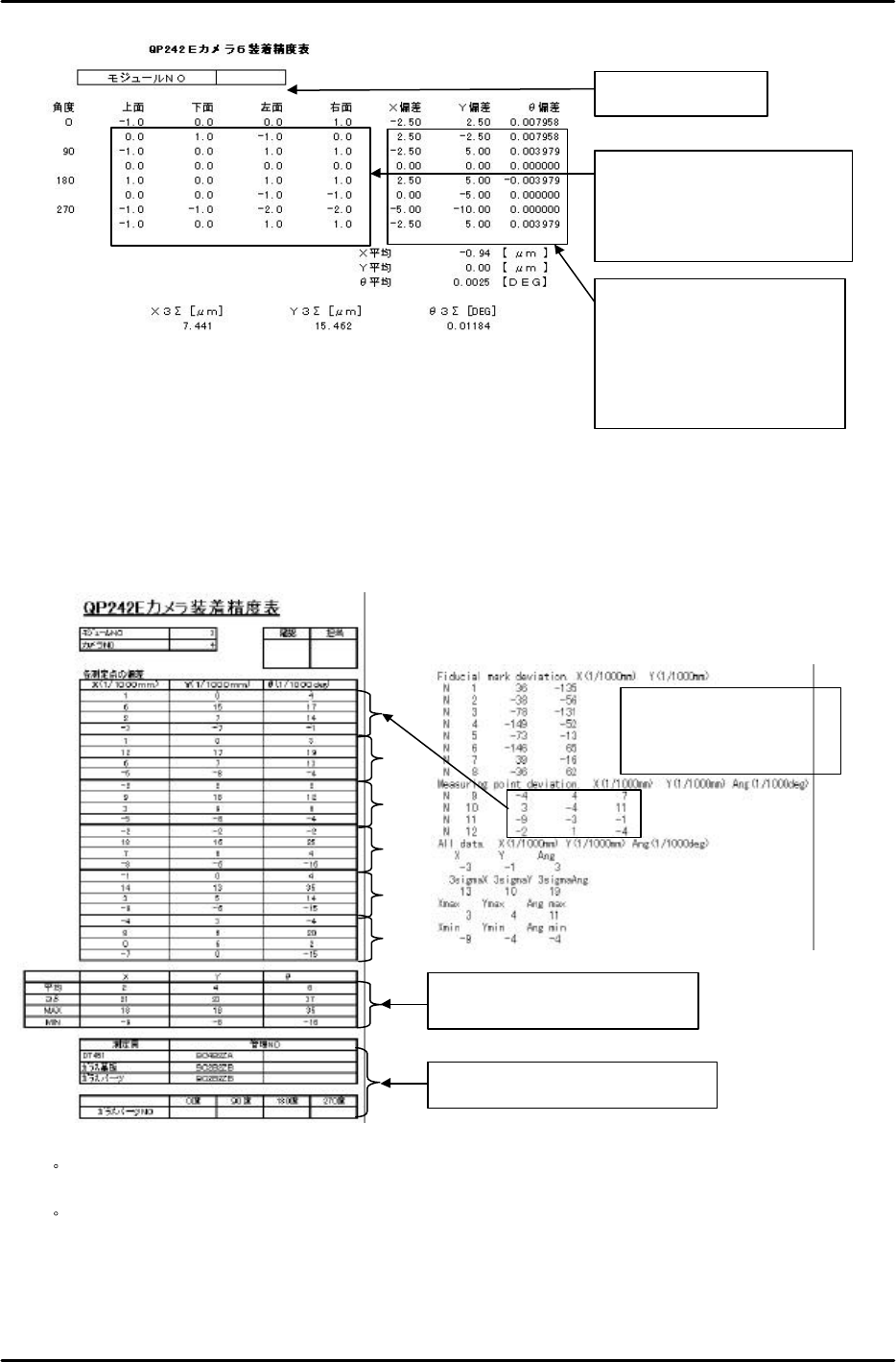
j ) If the placement accuracy falls within the allowable tolerance ranges then input the data
into a QP242E Camera 6 Placement Accuracy Table (Excel file: QP242E camera6placement
accuracytable.xls) and obtain a printout of the table.
Glass board for 60-pin parts
270degrees
270degrees
180degrees
180degrees 90degrees
90degrees
0degrees
0degrees
FK-9F98-07 QP242E Training Text for Service Engineers
6th edition 7. Static Accuracy Measurement [6/6]
Fuji Machine Mfg. Co., Ltd. Okazaki
SMT Equipment Quality Assurance Dept.
echnical Support Div. Section No.2
7-6
4) Results Tabulation
Once the placement accuracy of each camera type falls within the allowable tolerance
ranges, use the DT to carry out placement accuracy measurement six times (total of 24
points) in succession without changing the Proper data.
From the results enter the Measuring point deviation {X, Y, Ang (Q)} data in the
placement accuracy table (Excel file: Cameraaccuracystatisticstable.xls).
・ For camera type 1 since 32 points can be measured at one time, measurement does not
have to be repeated six times. One measurement (total of 32 points) completes the process.
・
For camera type 6 since eight points can be measured at one time, measurement is
completed after three rounds of measurement. For camera type 6 two glass parts are used
for each angle of the part.
1)
3)
4)
5)
6)
Does not have to be input since the
values are entered automatically.
Be sure to record the control number.
Results of measurement
using the DT for camera type
2, 3, 4, and 7
Input the deviation (number of
graduations). All other items are
calculated automatically and thus
do not need to be input.
Input the module No.
Enter this value in the placement
accuracy table created in the next
step 4).
Note: The Q value must be
converted into 1/1000 deg.
FK-9F98-07 QP242E Training Text for Service Engineers
6th edition 8. MTU6 Adjustment [1/16]
Fuji Machine Mfg. Co., Ltd. Okazaki
SMT Equipment Quality Assurance Dept.
Technical Support Div. Section No.2
8-1
[CHAPTER 8]
MTU6 Adjustment
Note: Cut the power to the machine before connecting the MTU. If the by-pass key is
inserted in the mechanical switch of the MFU specifications safety door, remove
the key and put it in the MTU cover. If the key is left inserted in the MFU
specifications switch this will disable the MTU front safety door by-pass key
which can lead to damage.
[8-1] Prior to Adjusting the MTU6
- Since layered stacking of trays is not possible on the MTU6, the number of part types that can be
loaded increases to between 50 and 100 types in comparison to the MTU7 (MTU7 can handle from
10 to 20 part types).
- On modules that use the MTU6 it is possible to switch from an MTU6 to MFU and vice versa.
When changing from an MTU6 to an MFU, safety fence replacement work is also included. Check
the specification manual and be aware that if this option is included a spare fence will also be
shipped. When an MTU6 is installed on an MFU module, in some instances Proper data
measurement will be necessary.
- When an MTU6 unit is connected to the machine, it must be connected with the machine in the
zero set complete status. Also verify that the shuttle jaw and tray holder do not interfere with each
other.
- When disengaging an MTU6 unit from the machine, separate the shuttle jaw and tray holder and
also verify that the shuttle is advanced forward before beginning work. The shuttle may be
damaged if it is at the retract limit. (Remove after carrying out the magazine replacement
command operation [POSITION], [MTU], [EXCHG MAG.], and press START.)
- MTU6 Specifications
Suitable machine : QP-242 600 type and 760 type
Number of part types that can be loaded : 50 types/50 levels (Large parts tray), 100
types/50 levels (Small parts tray)
Tray stacking : Not possible
Tray size : 335 x 250 mm (1part type/level)
160 x 250 mm (2 part types/level)
Minimum tray thickness : 4 mm
Maximum tray thickness : 7.8 mm (When stored in 10 mm pitch)
Maximum load weight per tray magazine : 400 g
Empty tray removal : Not possible
TY-axis : 0.0833 mm/Pulse (1 mm/12 Pulses)
TZ-axis : 0.01 mm/Pulse
Required number of magnets : New model 200, existing model 100 for total
of 300 magnets/MTU
[8-2] Timer Adjustment
Remove the MTU6 lower control box cover and set the timer on the relay board
positioned on the left side to "0.4".
Control box cover
OMRON H3FA-A
L
S
Timer
Set the timer two scale
graduations from S.
This is equal to a time
of 0.4 seconds.
Relay board