a3369b.pdf - 第127页
Communication Interfaces 118 VTK - TR -BA- 171e - 1 - User Man u al MDS 3080 -V 8.2 PLC - Interface: 15 - pin, Sub -D Fig . 31 : PLC Interface : 15 - pin , Su b -D The PL C inter f ace (illust rated above) work s on dig …
Communication Interfaces
VTK-TR-BA-171e-1 - User Manual MDS 3080-V
117
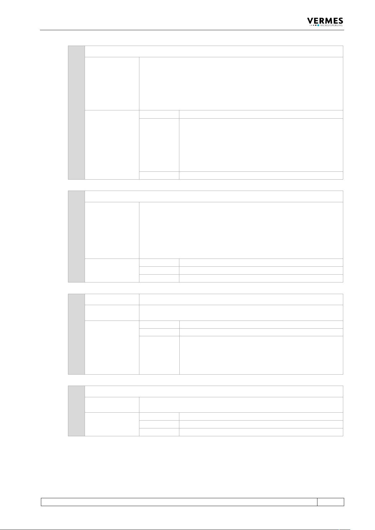
82 SETUP:AREAD:<setup no.>
Description:
This command reads the parameters of a given setup. As value you have to
enter its number.
All values relating to time, except “Falling” and “Rising”, are given in
1/10 ms (i.e. 10 ≙ 1 ms). Falling and rising are given in 1/100 ms (i.e. 100 ≙
1.00 ms).
The minimum values for Falling and Rising depend on the Needle Lift
(see
paragraph 7.4 "Minimum and Maximum Parameter Limits", page 61).
Example:
Input:
SETUP:AREAD:1
Result:
Displays the parameters of the given setup.
Rising: 30 ≙ 0.3 ms (ms = Milliseconds)
Open Time: 10 ≙ 1.0 ms
Falling: 15 ≙ 0.15 ms
Needle Lift: 90 %
Number of Pulses: 20
Delay: 8 ≙ 0.8 ms
Return:
30,10,15,90,20,8
83 BAUDRATE:0/1/2/3/4
Description:
This command changes the baud rate of the serial interface. There are five
possible baud rates (9600, 19200, 38400, 57600 and 115200),
corresponding with the parameters in this order (0, 1, 2, 3 or 4).
Important Note!
After reading the “OK”, the sender has to switch his baud rate as well;
otherwise, the communication will break down.
Example:
Input:
BAUDRATE:1
Result:
The baud rate is switched to 19200.
Return:
OK
84 GETTD GETTD = Get time and date
Description:
This command tells you the current time (UTC) and date in the format
“hour, minute, second, year, month, day”.
Example:
Input:
GETTD
Result:
The time (UTC) is given, including the date.
Return:
10,07,00,2019,02,17
or
No Clock (if the RTC of the MDC is defect)
85 MDC:RESTART
Description:
This command tells the MDC to shut down (without shutting down the
power) and then to restart.
Example:
Input:
MDC:RESTART
Result:
The MDC is shut down and then restarts.
Return:
OK
Communication Interfaces
118
VTK-TR-BA-171e-1 - User Manual MDS 3080-V
8.2 PLC-Interface: 15-pin, Sub-D
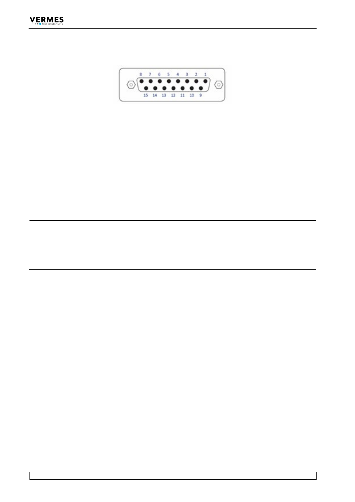
Fig. 31: PLC Interface: 15-pin, Sub-D
The PLC interface (illustrated above) works on digital basis without a particular syntax. It allows
for controlling a machine or device by means of a remote master device. Transmission of data is
possible in either direction. The trigger delay of this interface amounts to 96 μs.
Access is possible to:
• Status bits
• Values of voltage and current
• Set-Trigger signals initiating dispensing cycles (pulses) or complete packages of pulses
(bursts)
INFORMATION
Do not use keypad during PLC triggered dispensing
When a PLC-trigger is send, the keypad is locked at the same time. This lock can be lifted by
pressing the [enter]-key. But make sure not to do it during dispensing, since it also activates a
delay, which could affect your dispensing result. On the other hand, a trigger does not work, if
the MDC is not switched to the main menu. Additionally do not send a trigger, while the heater is
starting.
Communication Interfaces
VTK-TR-BA-171e-1 - User Manual MDS 3080-V
119
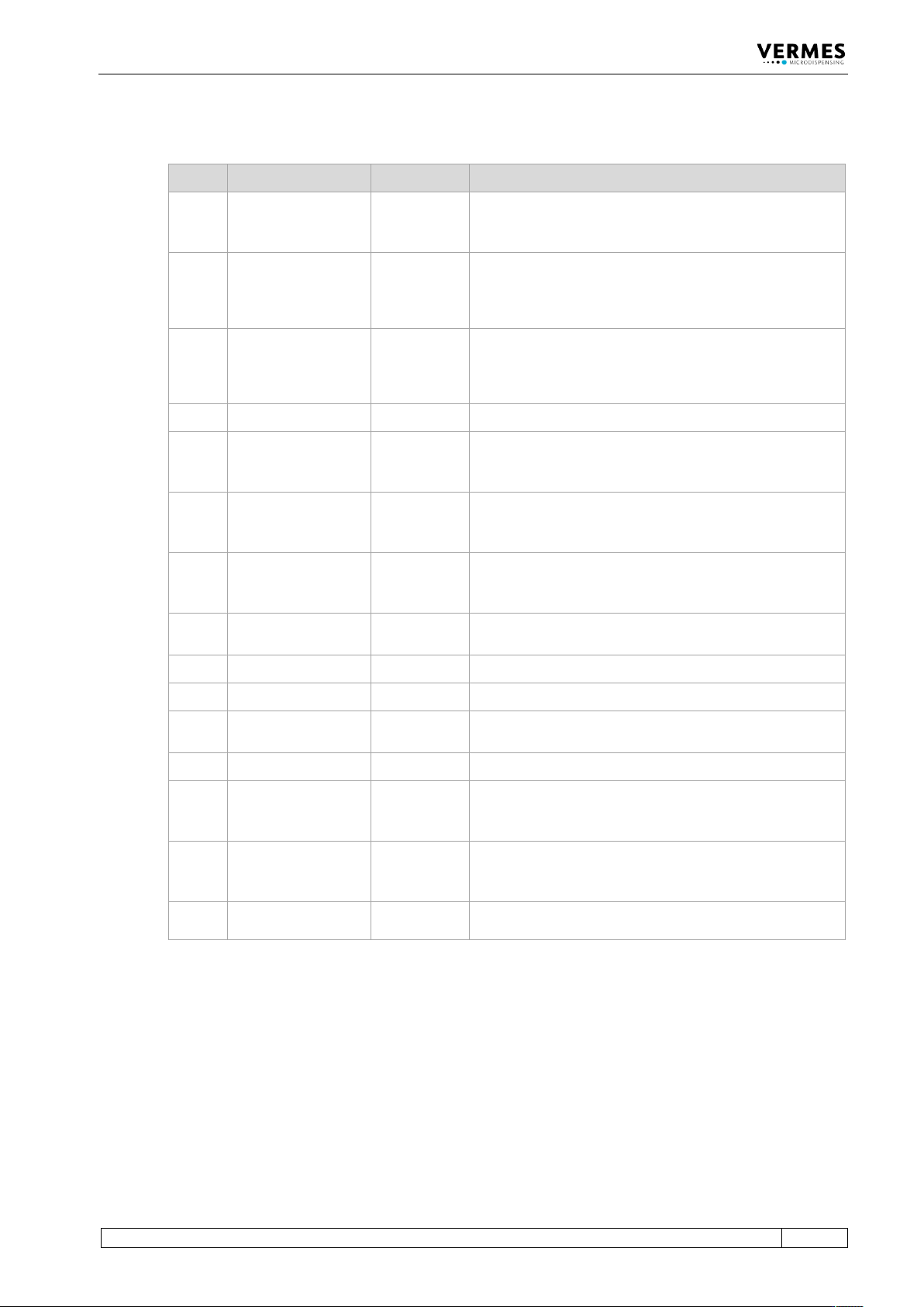
8.2.1 Pin Functions
PIN Characteristics Level Function
1
Output
0 / +24 V,
R
a
=2.2 kΩ
(valid for 0 V)
SingleDosOK
2
Input
0 / +24 V
R
i
=1.3 kΩ
Trigger Voltage Input
0 ... +5 V “Valve closed“
+12 V ... +30 V “Valve opened“
Positive edge triggering
3
Input
0/ +5 V
Ri
=400 Ω
Trigger Voltage Input
0 ... +0.8 V “Valve closed“
+3 V ... +5 V “Valve opened“
Positive edge triggering
4
Ground
___________
Ground
5
Output
0 / +24 V,
R
a
=2.2 kΩ
(valid for 0 V)
Set point Heating OK
6
Output
0 / +24 V,
R
a
=2.2 kΩ
(valid for 0 V)
Nozzle unit “adjusted” OK
(means green adjust LED)
7
Output
0 / +24 V,
R
a
=2.2 kΩ
(valid for 0 V)
Mains voltage OK
8
Output
0 … +5 V,
R
a
=20 kΩ
U-Needle – sensor signal (needle lift)
9
Output
24 V/50 mA
Power supply to external trigger
10
Ground
___________
Ground
11
Input
0 / 20 mA,
R
i
=500 Ω
Trigger Current Input
12
Reserved
___________
___________
13
Output
0 / +24 V,
R
a
=2.2 kΩ
(valid for 0 V)
For adjust: adjust failed. Nozzle unit screwed in too deep
or not enough.
Outside adjust: general error (24 V = error)
14
Output
0 / +24 V,
R
a
=2.2 kΩ
(valid for 0 V)
DosOK – Ready for dispensing (in the case of a pulse
package, at the end of the entire burst)
15
Input
___________
Trigger Abort, connection to ground, to interrupt
dispensing cycle