a3369b.pdf - 第183页
Attachments 174 VTK - TR -BA- 171e - 1 - User Man u al MDS 3080 -V 14.8 Changing the Adjust Ra nge The ra nge wh ere the gr een adj ust LE D is ON ha s for t echnical reasons a m inimum size of 5.8 µm. This range ca n be…
Attachments
VTK-TR-BA-171e-1 - User Manual MDS 3080-V
173
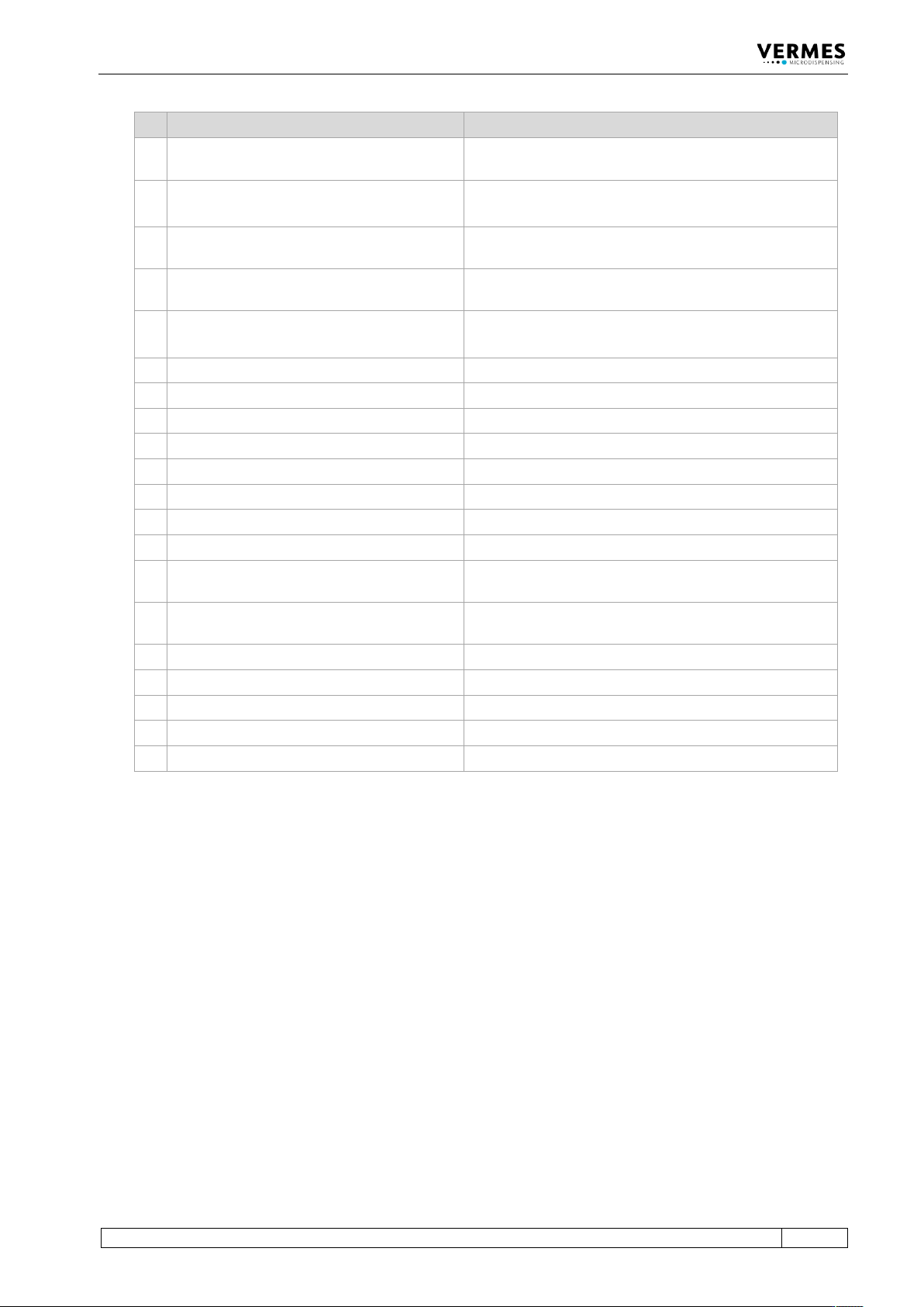
RS-232C commands Functions
66
SVALVE:OPEN:<RI>,<OT>,<FA>,<NL>,<NP>,<D
L>
Initiate a dispensing cycle with given parameters (“Rising”:
1/10 ms) (MDC returns the saved parameters)
67
SVALVE:OPENS<setup no.> Initiate a dispensing cycle with selected setup
(“Rising”: 1/10 ms) (MDC returns the saved parameters)
68
SVALVE:AOPEN Initiate a dispensing cycle with current parameters (“Rising”:
1/100 ms) (MDC returns the saved parameters)
69
SVALVE:AOPEN:<RI>,<OT>,<FA>,<NL>,<NP>,<
DL>
Initiate a dispensing cycle with given parameters (“Rising”:
1/100 ms) (MDC returns the saved parameters)
70
SVALVE:AOPENS<setup no.> Initiate a dispensing cycle with selected setup
(“Rising”: 1/100 ms) (MDC returns the saved parameters)
71
WRITE:LCD:<text> Write an ASCII text on the display
72
SCENARIO:STATUS Check the status of scenarios and PLCstops
73
SCENARIO:OFF Deactivate the use of scenarios
74
SCENARIO:ON Activate the use of scenarios
75
SCENARIO:PLCSTOP:1:OFF Deactivate the PLC-Stop
76
SCENARIO:PLCSTOP:1:ON Activate the PLC-Stop
77
SCENARIO:SAVE:<scenario no.>:<values> Save the parameters for selected scenario
78
SCENARIO:READ:<scenario no.> Check the parameters of selected scenario
79
SETUP:SAVE:<setup
no.>:<RI>,<OT>,<FA>,<NL>,<NP>,<DL>
Save parameters in a setup (“Rising”: 1/10 ms)
80
SETUP:ASAVE:<setup
no.>:<RI>,<OT>,<FA>,<NL>,<NP>,<DL>
Save parameters in a setup (“Rising”: 1/100 ms)
81
SETUP:READ:<setup no.> Check the parameters of a setup (“Rising”: 1/10 ms)
82
SETUP:AREAD:<setup no.> Check the parameters of a setup (“Rising”: 1/100 ms)
83
BAUDRATE:0/1/2/3/4 Change the baud rate
84
GETTD Check the current time and date
85
MDC:RESTART Restart the MDC
Attachments
174
VTK-TR-BA-171e-1 - User Manual MDS 3080-V
14.8 Changing the Adjust Range
The range where the green adjust LED is ON has for technical reasons a minimum size of 5.8 µm.
This range can be expanded by using the serial command “ADJUST:TO:CHANGE:<range>” (see
paragraph 8.1.2.2 "Explanations", page 88). This attachment explains the details.
IMPORTANT INFORMATION
Changing the adjust range can lead to leakages
Changing the adjust range is only recommended for selected applications in the fixed adjust
mode. You should contact our technical support first, since sometimes widening the adjust
range can lead to leakage despite a successful adjust.
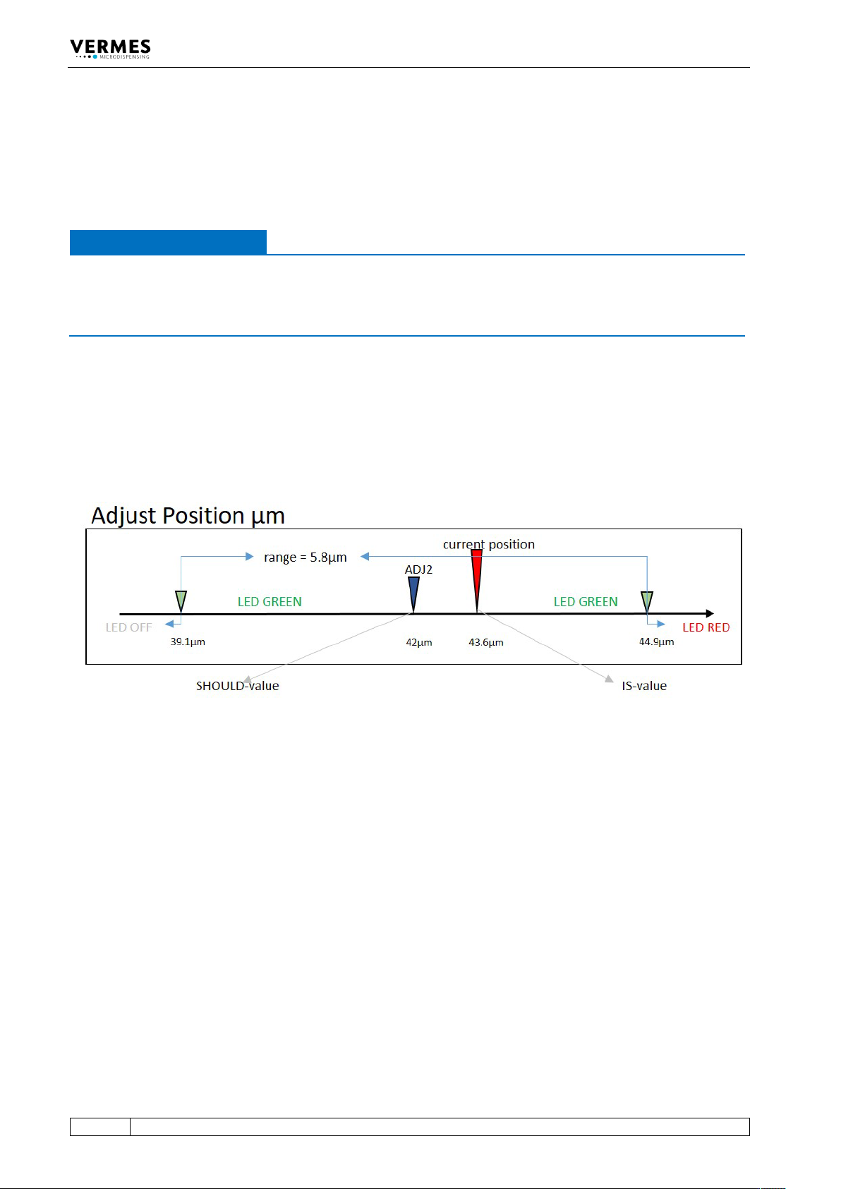
The adjust range has the setpoint ADJ2 (the “SHOULD-value”) in its center (see Fig. 50). When the
current position of the adjust (the “IS-value”) is within the adjust range, the green adjust-LED is
ON. Is the current position beyond the adjust range the red adjust-LED is ON. In case the value for
the current position is smaller than the value where the adjust range begins both adjust-LEDS are
OFF.
With the serial command ADJ:VALUES:?, the MDC shows you the setpoint ADJ2 as well as the
deviation of the current position from the setpoint (see paragraph 8.1.2.2, page 88).
Fig. 50: Adjust position with unchanged adjust range
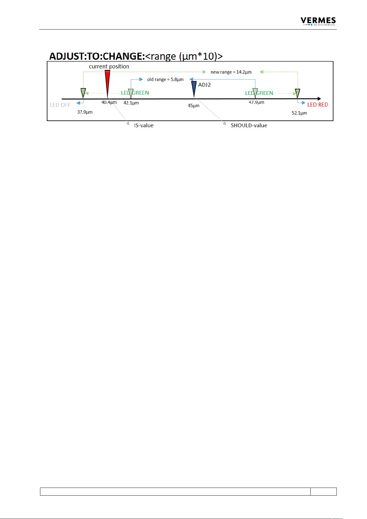
To widen the adjust range, use the serial command ADJUST:TO:CHANGE:<adjust range>. As
parameter for the range, enter ten times the value in micrometer. E.g. to change the adjust range
to 8.4 µm, enter 84 as value for the parameter. The new adjust range is again centered around
the setpoint ADJ2. The following figure shows an example, where the adjust range is set to
14.2 µm (see Fig. 51). The range is then at 45 µm +/- 7.1 µm. In this example, the command would
be ADJUST:TO:CHANGE:142.
You can only enter integer values between 58 and 300 as parameters (i.e. between 5.8 µm and
30.0 µm).
Attachments
VTK-TR-BA-171e-1 - User Manual MDS 3080-V
175
Fig. 51: Adjust position with adjust range changed with command ADJUST:TO:CHANGE