a3369b.pdf - 第46页
Micro disp en sing Va lve VTK - TR -BA- 171e - 1 - User Manua l MDS 3080 -V 37 5.2 Explo sion V iew V alve The exp losion view of a n MDV 3080 -V . Fig . 13 : Explos ion vi ew valve 1 Cab le connection s (red actuato r, …
Microdispensing Valve
36
VTK-TR-BA-171e-1 - User Manual MDS 3080-V
sensor, the piezoelectric element and the mechanics to drive the tappet. Actuator case and
mechanics are sealed for protection against dust and contamination.
At the bottom of the valve is the inlet where the tappet (2) runs. You can exchange the tappet.
Powered by the actuator the tappet moves with high speed back and forth. It hits the dispensing
medium and presses it through the opening of the nozzle insert. Tappets can be made of
ceramics or of carbide metal. They can have different forms or sizes. A tappet should be checked
and cleaned regularly or exchanged if necessary (see paragraph 6.2 "First Assembling of the
Valve", page 41). The adjust screw (8; see paragraph 5.2, page 37) is at the top end of the valve
body.
The connection between valve body and fluid box is made up of the tappet sealing (3). There are
different types of tappet sealings, e.g. the Tappet Sealings PE and PTFE. These tappet sealings
have to be used together with a tappet centering piece.
A small but important module is the nozzle insert (4), which has to be considered as a wearing
part. Thanks to the bayonet fluid box, it can easily be cleaned and exchanged in case of need.
VERMES Microdispensing offers a large selection of different nozzle inserts to allow for optimum
dispensing results, according to the current application. They can differ in form and material.
The nozzle fixation nut (5) contains the nozzle insert (NI).
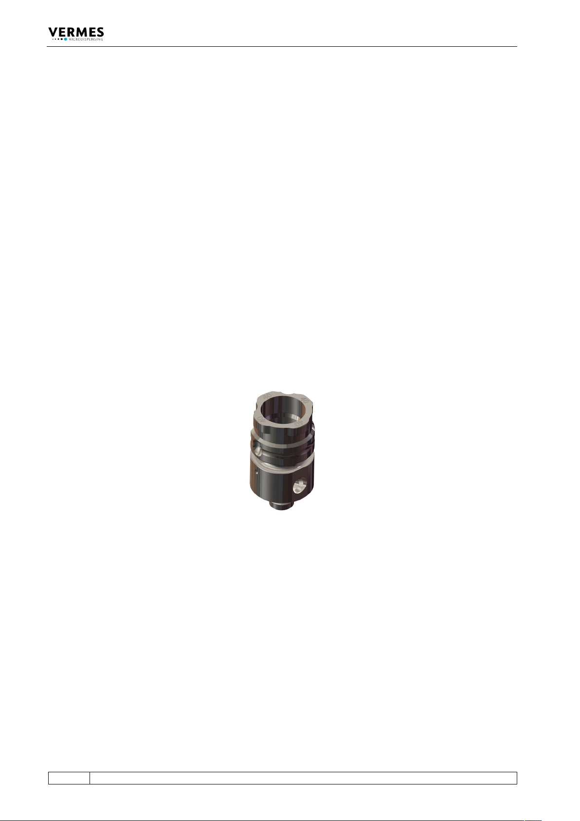
The fluid box (6) contains the Fluid Box Body MDF 1500-BY-40 (order no. 1014538, see Fig. 12).
Information how to assemble a fluid box you can find in paragraph 6.2, page 41.
The media supply (7) supplies the dispensing medium and is connected with the fluid box.
VERMES Microdispensing has many different configurations available (see paragraph 13.4,
page 160). For smaller amounts to be dispensed you can use a cartridge. They come in different
sizes and types. For larger amounts, you can use a tube connector to connect a pressure tank
with the fluid box.
Fig. 12: Fluid Box Body MDF 1500-BY-40
Microdispensing Valve
VTK-TR-BA-171e-1 - User Manual MDS 3080-V
37
5.2 Explosion View Valve
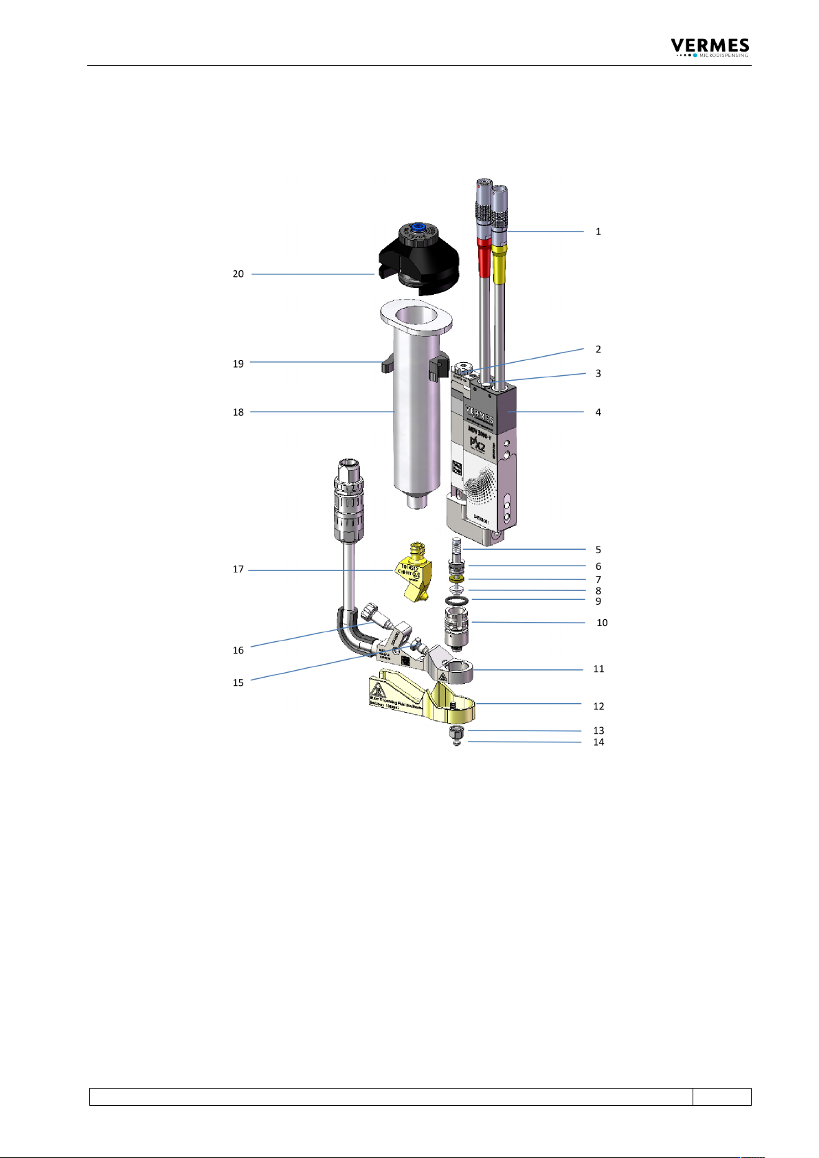
The explosion view of an MDV 3080-V.
Fig. 13: Explosion view valve
1 Cable connections (red actuator,
yellow sensor)
2 Adjust screw
3 Compressed air (in and out)
4 Valve MDV 3080-V
5 Tappet rod with tappet spring
6 Tappet centering screw BY
7 Tappet centering piece
8 Tappet sealing
9 O-ring BY
10 Fluid box body MDF 1500-BY
11 Heater MDH-48-BY
12 Isolation body
13 Nozzle fixation nut
14 Nozzle insert
15 Connector BY
16 Tightening screw
17 Cartridge base CHI
18 Cartridge
19 Cartridge holder
20 Adapter Safe for compressed air
(connection for cartridge)
Microdispensing Valve
38
VTK-TR-BA-171e-1 - User Manual MDS 3080-V
5.3 Technical Data
Parameter Value
Dispensable Quantity
Minimum 3 nl per cycle
Inlet Pressure Range
Depending on the supply unit
(e.g. cartridge or pressure tank)
Dynamic Viscosity of Fluids
Low to medium viscosity up to 8000 mPas
Response Time (PLC-interface)
ca. 96 µs
Dispensing Frequency (max.)
< 2 kHz
Dispensing Frequency (average)
450 Hz
Compatibility
all aqueous fluids, organic solvents, weak acids and
bases
Dimensions (basic model)
103 mm x 44 mm x 15 mm
Weight
ca. 260 g (depending on configuration)
Position of Tappet in Absence of Voltage
closed