a3369b.pdf - 第62页
Initial Operation VTK - TR -BA- 171e - 1 - User Manua l MDS 3080 -V 53 Preparations for the a djust: 1 Tur n th e adjust sc rew by using th e tool MDT 327 complet ely in the di rection “ open” (see arrow on the v alve) .…

Initial Operation
52
VTK-TR-BA-171e-1 - User Manual MDS 3080-V
6.5 The Adjust Process
This chapter explains the adjust, which for a valve of the MDV 308x series is a top adjust. The
adjust is necessary for all valves. A thoroughly performed adjust is the basis for clear and
reproducible dispensing results.
This paragraph describes the normal adjust. You can also control the adjust via the serial
interface as remote adjust (see paragraph 8.2.3 "Remote Adjust", page 123).
The microdispensing system is unable to perform a regular repeatable process, if the nozzle
insert is not properly positioned relatively to the tappet prior to dispensing. Therefore, you have
to perform the adjust during initial operation and after each exchange of the nozzle unit. This is
especially important to avoid any leakage during dispensing.
IMPORTANT NOTE
Cleaning before adjust
The system has to be cleaned thoroughly before the adjust. The presence of dirt particles
jammed between the tappet surface and the nozzle insert would compromise the results.
Especially the O-ring-N around the tappet guidance has to be free of grease and dirt (for
information regarding the cleaning see paragraph 9, page 129).
IMPORTANT NOTE
Heating and adjust
In case your application uses a nozzle heater, you have to activate the heater before you start the
adjust. Make sure to wait long enough for the heater to reach stable temperature, since the
adjust could lead to an incorrect result otherwise.
Wear heat-resistant gloves while working with the valve!
INFORMATION
Abort and end of procedure, fixed adjust mode
• The adjust can be aborted at almost any time by pressing [esc]. The exception is when the
green adjust LED is ON.
• In fixed adjust mode (see paragraph 7.12, page 76) the range for the adjust is different (0 – 50
µm instead of 0 – 4 µm).
• The range, where the green adjust LED is ON, has for technical reasons a minimum size of
5.8 µm. This range can be expanded by using the serial command
“ADJUST:TO:CHANGE:<range>” (see paragraph 14.8 "Changing the Adjust Range", page 174).
This change is only recommended for selected applications in the fixed adjust mode. You
should contact our technical support first, since sometimes widening the adjust range can
lead to leakage despite a successful adjust.
Picture Explanation
Initial Operation
VTK-TR-BA-171e-1 - User Manual MDS 3080-V
53
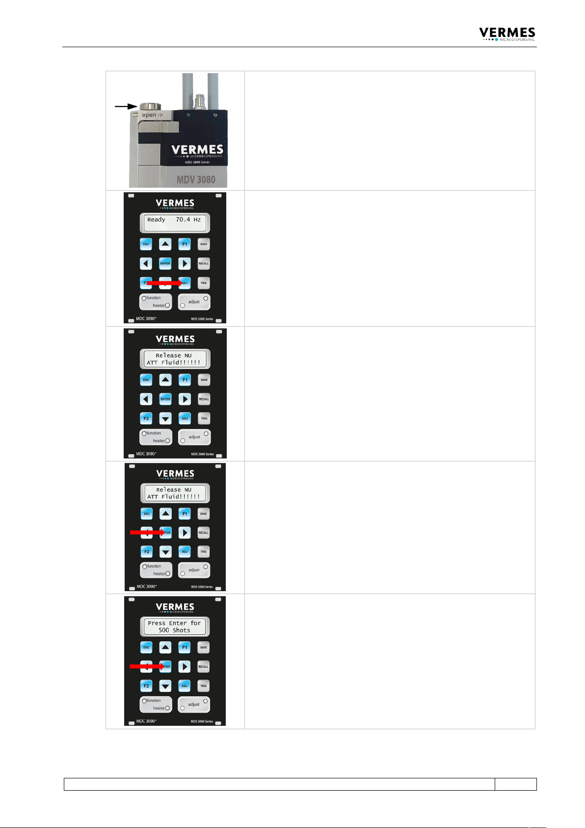
Preparations for the adjust:
1 Turn the adjust screw by using the tool MDT
327 completely in the direction “open” (see
arrow on the valve). Alternatively, you can use
the MDT 306 - Torque Wrench Tool VM with Bit
VM-A.
2 Mount the tappet.
3 Mount the complete fluid box and the nozzle
fixation nut and screw it tight.
You start the adjust by pressing [adj] on the keypad of the control
unit.
The message “Release NU ATT Fluid!!!!!!” appears in the display (NU =
Nozzle Unit).
Confirm by pressing [enter] that the adjust screw is completely open.
The display now shows “Press Enter for 500 Shots”. These shots help
to prepare the valve for the adjust. Confirm by pressing [enter].
Initial Operation
54
VTK-TR-BA-171e-1 - User Manual MDS 3080-V
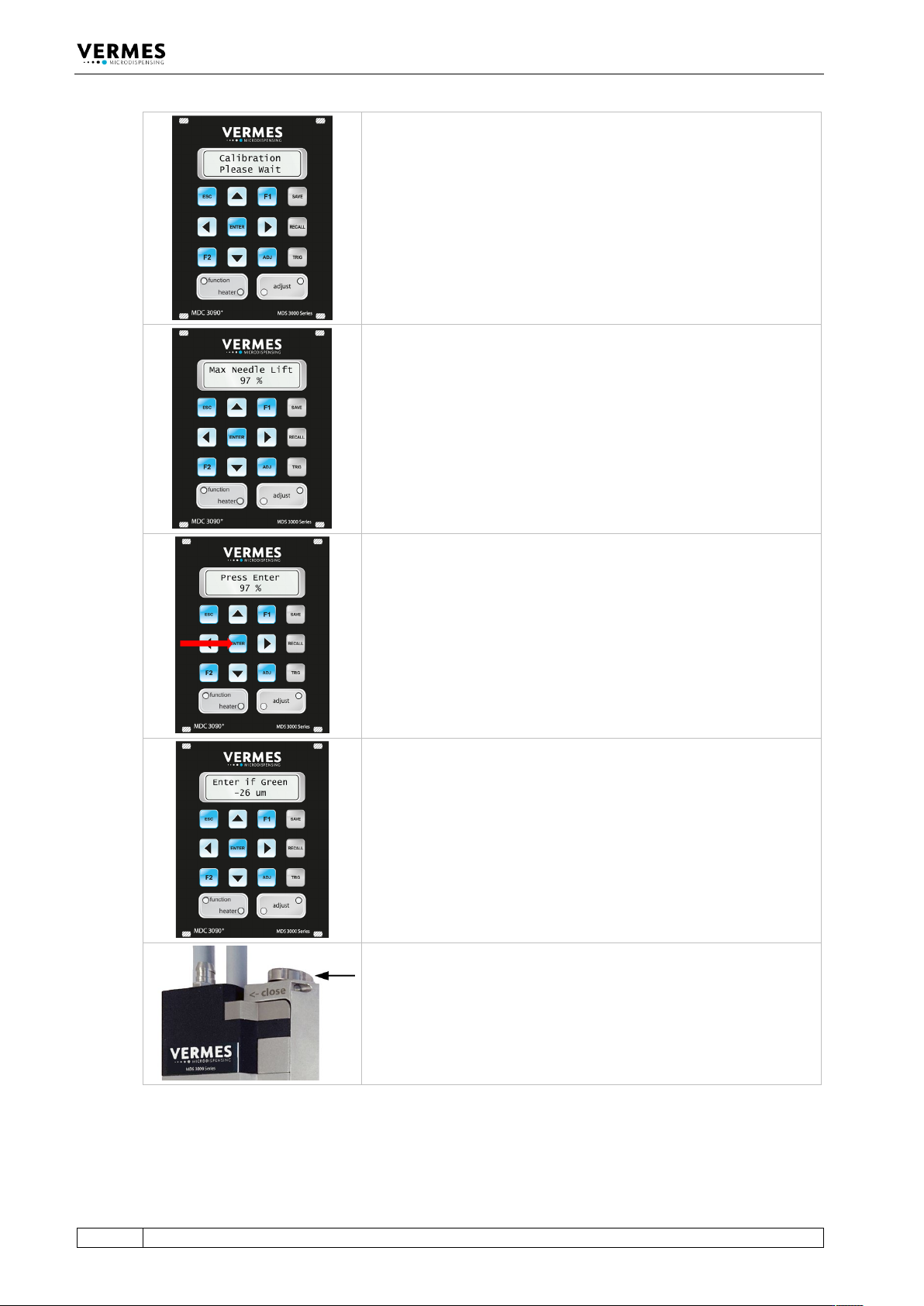
The display shows “Calibration Please Wait”. This can take a few
moments. Please wait.
At the end of the calibration, the system tests the performance of the
valve. If the performance is below 100 % and therefore unsatisfactory,
the display shows for a moment the message “Max Needle Lift”
together with a percentage value of the valve performance for the
attached valve. In this case, you should send the valve to VERMES
Microdispensing GmbH for maintenance.
If the quality of the valve is okay, this message will not be shown.
In the display, the message changes from “Max Needle Lift” to “Press
Enter”. Press the [enter]-key.
If the quality of the valve is okay, this message will not be shown. You
will reach the next step without pressing [enter].
The display shows the starting value of the adjust.
Now turn the adjust screw with the help of tool MDT 327 slowly in
the direction “close”, until the green adjust LED is ON. The adjust is
possible between 0 µm and 4 µm. (In fixed adjust mode, the adjust is
possible between 0 µm and 50 µm.)