a3369b.pdf - 第32页
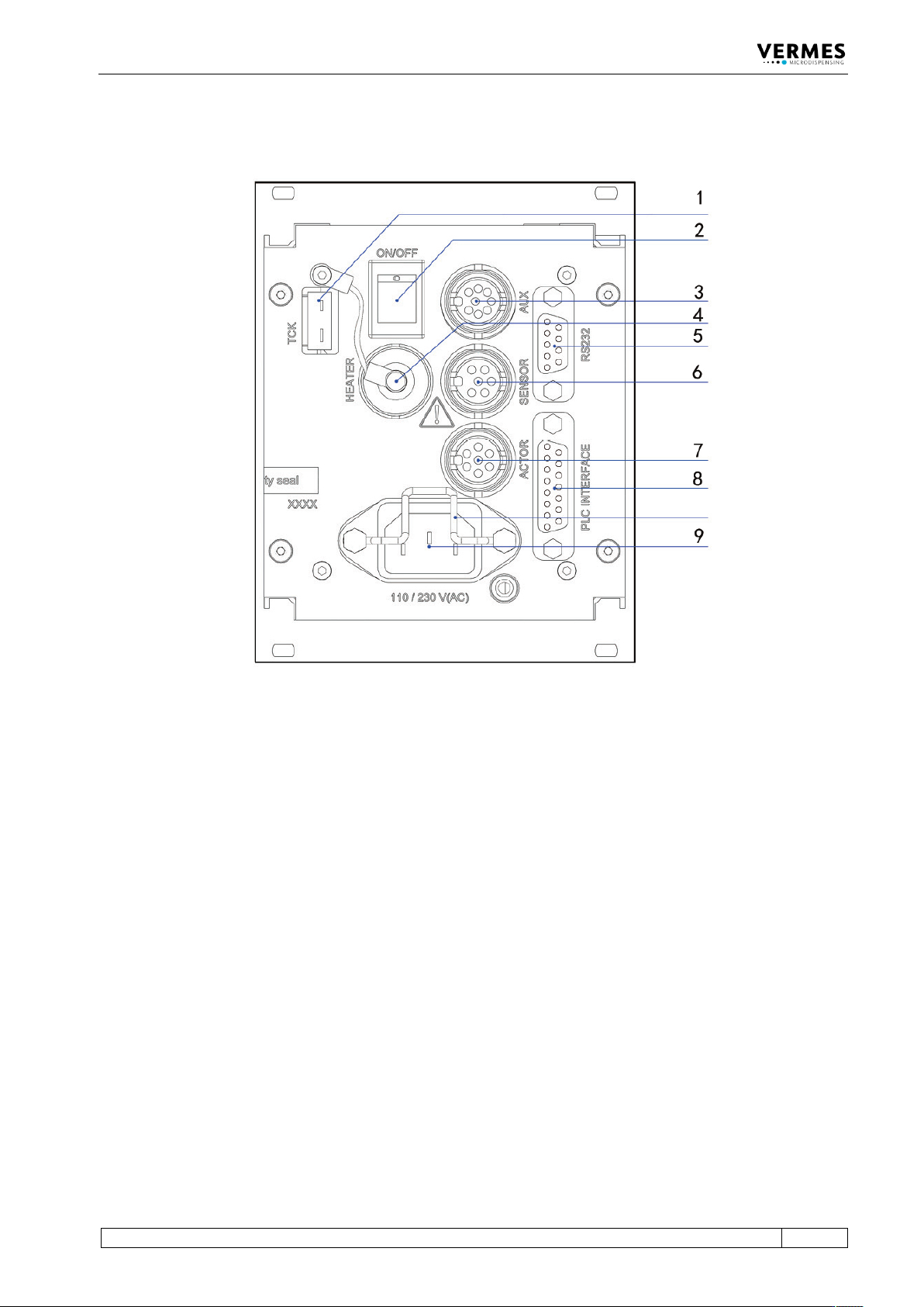
Control Unit MDC VTK - TR -BA- 171e - 1 - User Manua l MDS 3080 -V 23 4.3 Back Sid e Fig . 2: Back s ide 1 Th ermocoup le „Type K“ socket 2 Main s swi tc h 3 AUX socket 4 Sock et for heat ing 5 RS - 232C int erface (9 - …

Control Unit MDC
22
VTK-TR-BA-171e-1 - User Manual MDS 3080-V
You can de-/activate the control lamps for adjust. It makes no difference during the adjust (as
above). But it affects the lamps outside of the adjust (as below).
Outside of the adjust: (if the control lamps for adjust are activated)
• Red: the MDC detects an error.
• Green: the valve detects that the adjust value falls inside the adjust range.
Outside of the adjust: (if the control lamps for adjust are deactivated)
• Red: the MDC detects an error (except for an adjust error).
• The green adjust-LED stays OFF.
To de-/activate the control lamps for adjust, enter the service code 1100 (see paragraph 4.5.6
"Submenu “Service-Option”", page 33). Alternatively, you can use the serial command
SETADJLED:OFF/ON (see paragraph 8.1.2.2 "Explanations", page 88).
Control lamp for status of heating:
This red LED indicates the activity of the heating.
Heating activated – LED ON
Heating deactivated – LED OFF
Heat-up phase – LED flashes
Control Unit MDC
VTK-TR-BA-171e-1 - User Manual MDS 3080-V
23
4.3 Back Side
Fig. 2: Back side
1 Thermocouple „Type K“ socket
2 Mains switch
3 AUX socket
4 Socket for heating
5 RS-232C interface (9-pin)
6 Sensor socket
7 Actuator socket
8 PLC-interface (15-pin)
9 Mains connector
Thermocouple socket (TCK):
This element is intended for connection of thermocouples “Type K“.
Mains switch:
By means of this illuminated switch, the unit is switched ON and OFF.
AUX socket:
This connector can be used for supply of an external device (e.g. an optocoupler) or to control
certain parameter setups or scenarios (see paragraph 7.9.3 "Scenario Selection with Select Pins",
page 67). It is one of the three interfaces of the control unit (see paragraph 8.3, page 128 for the
pin assignments).
Actuator socket:
For the connection of the actuator cable.

Control Unit MDC
24
VTK-TR-BA-171e-1 - User Manual MDS 3080-V
Sensor socket:
For the connection of the sensor cable.
Socket for heating:
The heater cable has to be connected here.
PLC-interface (15-pin):
Different inputs and outputs may be connected. For the communication protocol, refer to
paragraph 8.1.1, page 83.
RS-232C interface (9-pin):
Since the system offers the possibility of external programming of dispensing parameters via PC,
a local RS-232C is integrated to receive the data. For the communication protocol, refer to
paragraph 8.2.1, page 119.
Mains connector:
Connects the control unit to power supply.