a3369b.pdf - 第28页
G eneral Instr uctions VTK - TR -BA- 171e - 1 - User Manua l MDS 3080 -V 19 3.3.10 MDT 30 6 - Torque Wrench Tool VM b lack The MDT 306 allows you to s crew t i ght scr ews with an ex actly set t i ghteni n g torqu e. The…

General Instructions
18
VTK-TR-BA-171e-1 - User Manual MDS 3080-V
3.3.9 Hexagon Key Set
The set includes three hexagon keys (sizes 2, 2.5 and 3) for hex-screws, with blades made of
hardened steel and ergonomic grips.
Intended Purpose:
1. Mounting and demounting the fluid box (2)
2. Mounting and demounting the tappet guard (2)
2. Mounting and demounting the isolation body (2)
4. Mounting and demounting the cartridge holder (2 or 2.5, depending on
type)
5. Fixing of the valve, in-situ (3)
Tab. 14: Hexagon Key Set (Order no. 1012993)
General Instructions
VTK-TR-BA-171e-1 - User Manual MDS 3080-V
19
3.3.10 MDT 306 - Torque Wrench Tool VM black
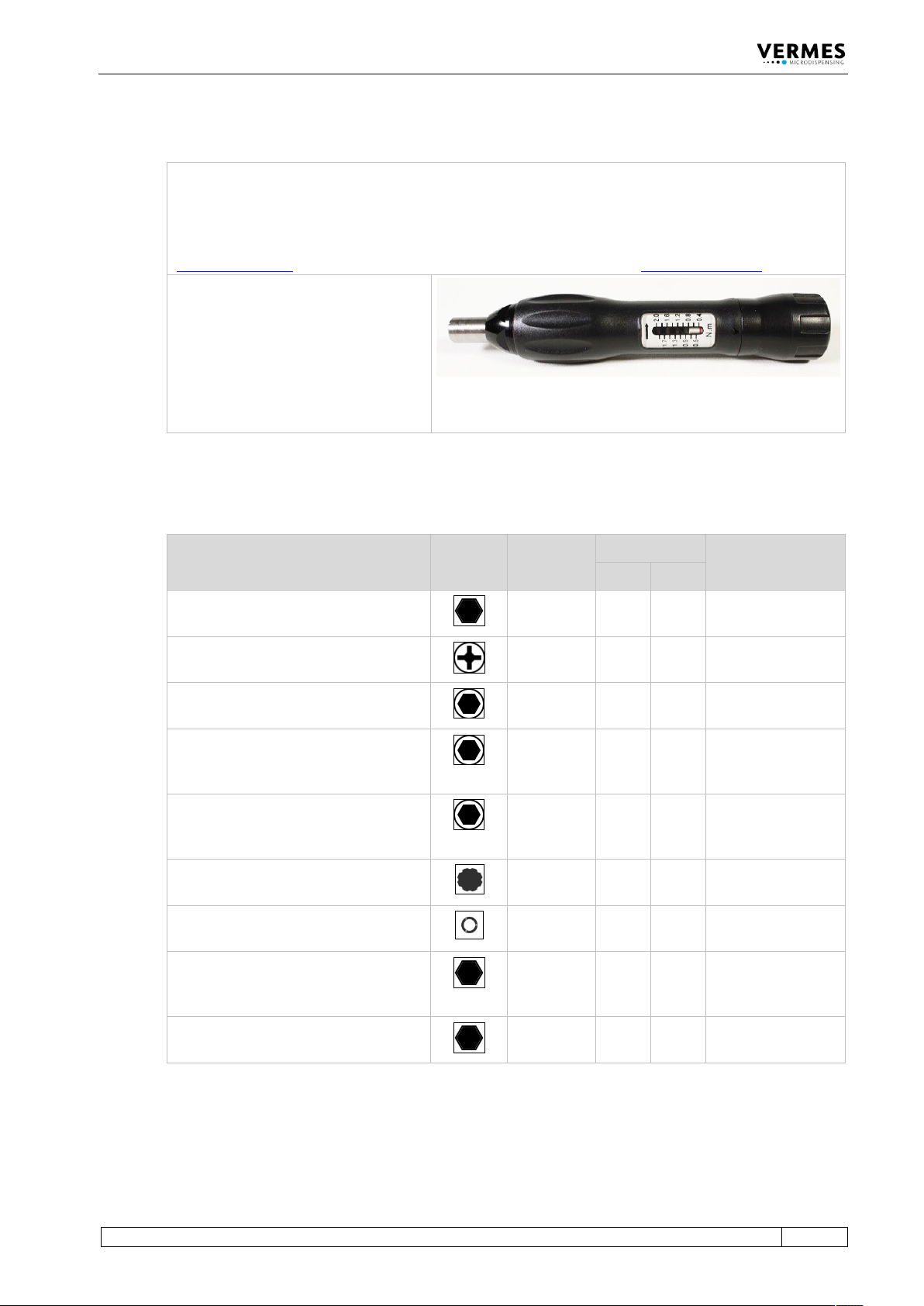
The MDT 306 allows you to screw tight screws with an exactly set tightening torque. The value can be
adjusted continuously at the torque wrench tool.
You can order the necessary bits separately or together with the torque wrench as a set in a tool box
(MDTS 1 - Torque Wrench Tool Set TA, order no. 1013521). Additional information is in the Quick
Reference Guide “Torque Wrench Tool VM MDT 306”. You can download it from the VERMES homepage
(www.vermes.com). The necessary password you can get from our sales (sales@vermes.com
).
Intended Purpose:
1. Tightening screw
2. Tappet Centering Screw BY
3. Cartridge holder
4. Fluid box connector Luer-Lock
5. Nozzle Fixation Nut
6. MDC front panel
7. Valve screws
Tab. 15: MDT 306 - Torque Wrench Tool VM (Order no. 1015062)
3.3.11 Torques (in cN.m)
Element Gearing
Profile
Bit
Order No.
Torque (cN.m) Cross Reference
Min. Max.
Nozzle Fixation Nut
(hexagon screw, size 7)
1014204
150
180
Page 35
Screws for valve fixation
(size M4, thread depth 5 mm)
1013373
150
180
Page 46
Screw for cartridge holder M 2 x 4
(hexagon socket, size 2)
1013294
25
30
Page 41
Connector BY
(in mounting body PEEK; hexagon
socket, size 2.5)
1016631
70
80
Page 41
Connector BY
(in metal mounting body; hexagon
socket, size 2.5)
1016631
120
140
Page 41
Tightening screw stainless steel
(gearing VM-A)
1014519
120
140
Page 37
Tappet centering screw BY
(gearing VM-B)
1014521
100
140
Page 41
Fluid box connector Luer-Lock
(stainless steel; hexagon screw, size
M8)
1013374
100
120
Page 41
Fluid box connector Luer-Lock
(PEEK; hexagon screw, size M8)
1013374
40
60
Page 41
Tab. 16: Torques (in cN.m)
Control Unit MDC
20
VTK-TR-BA-171e-1 - User Manual MDS 3080-V
4 Control Unit MDC
This chapter contains relevant information about the control unit. It describes the menu
structure, keypad and functions of the control unit.
4.1 Technical Data
Value
Dimensions
128 mm H x 102 mm W x 173 mm D (w/o Kabel)
(see dimensional drawing, Page 166)
3 RU x 20 HP
Weight
ca. 1500 g
Supply Voltage
110/230 V AC/DC
Supply Frequency
50/60 Hz
Current Consumption
Max. 900 mA
During start-up, this value can increase by a factor
of 5 (start-up peak).
Recommended fuse: 16 A for 240 V resp. 110 V
Ambient Temperature
10 °C - 50 °C
Air Humidity
The relative humidity rH might not surpass 80% at
31 °C or 50% at 50 °C (connect linearly for other
temperatures).
Casing Type
Plug-in case for 19“ rack
Color of Casing
Black
Ventilation
Convection
Internal Storage Locations:
10
Display Lines
2 lines with 16 characters each
Display Color
White with background lighting
Keypad
12 softkeys
Color of Keys
Blue, beige
Control Lamps (Front)
1x Heating circuit (red)
1x First Drop (“function”, red)
1x Adjust OK (green)
1x Adjust not OK (red)
Control Lamps (Back)
1x Illuminated power lamp
Plug Contacts (Back)
1x Mains plug (110/240 V AC)
1x 9 pin Sub-D RS-232C
1x 15 pin Sub-D PLC
1x AUX-socket 24V
1x Sensor socket
1x Actuator socket
1x Socket for heating
1x Thermocouple socket