a3369b.pdf - 第40页
Control Unit MDC VTK - TR -BA- 171e - 1 - User Manua l MDS 3080 -V 31 4.5.4 Submenu “ Status ” You can use this subm enu to switch “FixedAdjust” and “Fi rstDrop” ON or OFF (see paragrap h 7.12 , page 76 and para graph 7.…
Control Unit MDC
30
VTK-TR-BA-171e-1 - User Manual MDS 3080-V
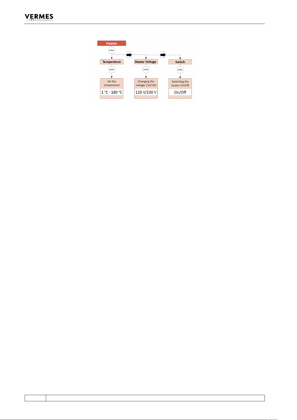
Fig. 6: Submenu “Heater” (inapplicable)
Control Unit MDC
VTK-TR-BA-171e-1 - User Manual MDS 3080-V
31
4.5.4 Submenu “Status”
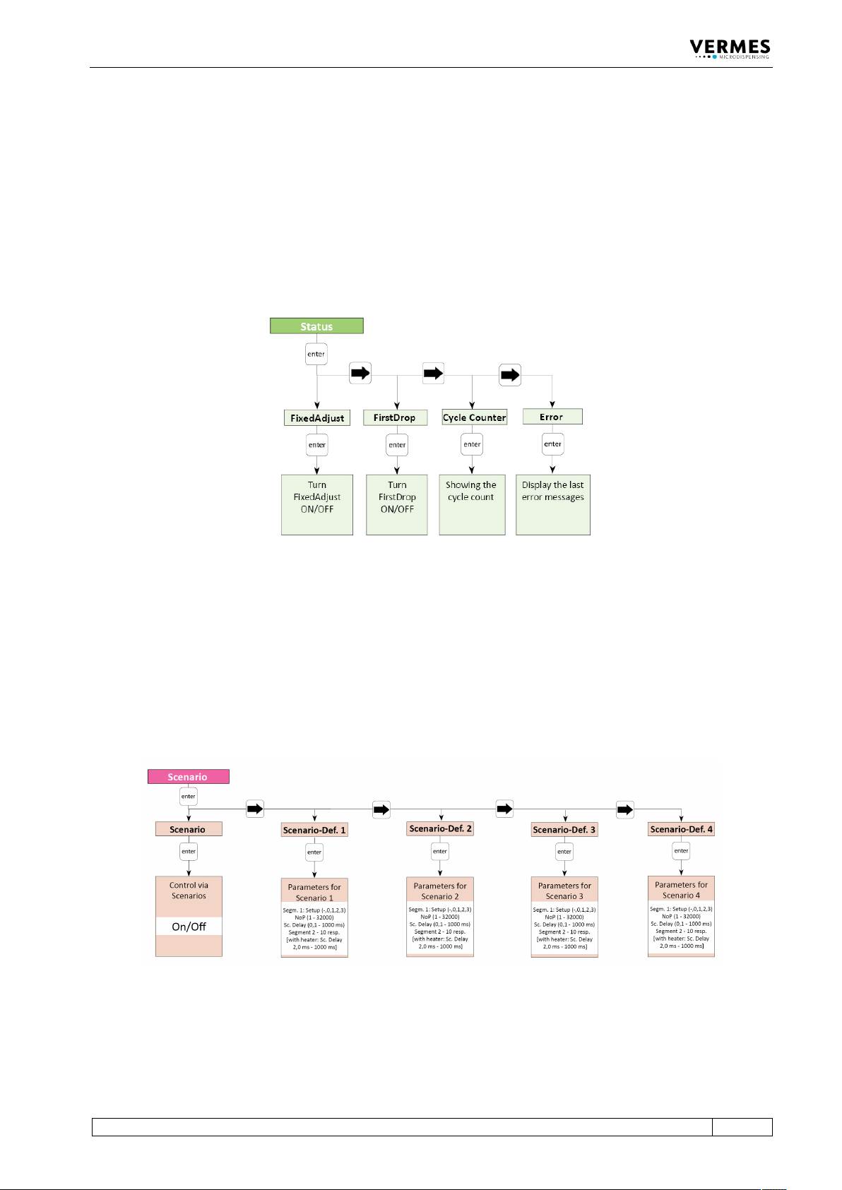
You can use this submenu to switch “FixedAdjust” and “FirstDrop” ON or OFF (see
paragraph 7.12, page 76 and paragraph 7.11, page 71). If you switch “ON” either of these modes,
the red first drop LED shines until you have performed a successful first drop adjust. If you switch
“ON” “FixedAdjust”, you also need to perform a normal adjust.
With “Cycle Counter”, you can check the cycle count of the dispensing cycles.
“Error” shows the latest error messages of the system (up to 50), depending on the system even
with date and time (UTC). Help to solve error messages you will find in paragraph 11.2, page 151.
Fig. 7: Submenu „Status“
4.5.5 Submenu “Scenario”
In the submenu “Scenario” you decide if you want to work with scenarios (see paragraph 7.9.1
"Basics about Scenarios", page 66). You can also enter parameters for pre-defined scenarios. Each
of the four potential scenarios has its own submenu, where you can set those parameters. The
second diagram explains the structure of these submenus. Check there to find the possible limits
for those parameters.
With [→] and [←] you can switch between the four scenarios.
Fig. 8: Submenu “Scenario”
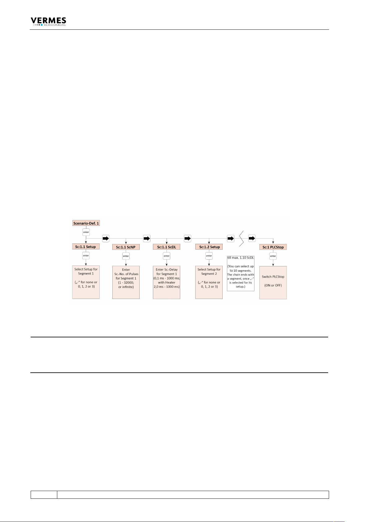
To enter the parameters for a scenario, press [enter] on the respective submenu “Scenario-Def.”
The structure of these submenus is explained in the picture below (see Fig. 9, page 32).
Control Unit MDC
32
VTK-TR-BA-171e-1 - User Manual MDS 3080-V
In “Sc:1.1 Setup” you can enter “0”, “1”, “2” or “3” to select a setup or “-”, to decide that no further
segment will follow. “0” is the working configuration, “1” to “3” are the parameters of the
respective setups 1 to 3. Then the scenario will end with this segment and the menu will stop
here as well. (If you later change the “-” to the number of a setup, the following segment will be
unlocked again in the menu.) If you set the blank directly in the first segment, the system will
simply use the working configuration instead of the scenario.
After entering a setup and [→], you can select the Number of Pulses next. This NP replaces the
one from the setup, which would be otherwise used. Another [→] gives the option to enter a
scenario delay. Standard value is 10 ms. Just as with the normal delay, with a heater connected to
the system the minimum scenario delay increases from 0.1 ms to 2.0 ms.
Another [→] brings you to the second segment in your scenario (“Sc:1.2 Setup”), where you have
the same options as with the first. All in all, you can combine up to ten segments (though only
four different setups, since only setups 0 to 3 are available), each with its own NP and scenario
delay, unless you stop your scenario beforehand by selecting “-” instead of a setup. After the last
segment, another [→] brings you the option to set the PLC-Stop “ON” or “OFF”. With “ON” a
scenario always ends automatically, once the trigger signal drops to “low”. No further segments
of the scenario will be performed. With the PLC-Stop “OFF”, the trigger signal only matters, if the
NP in a setup is set as “infinite”. With these parameters will be dispensed until the trigger signal
drops to “low”. If the trigger signal is already “low” when reaching the signal, only one pulse will
be shot. Then the next segment of the scenario will follow after the scenario delay (unless, of
course, it was already the last segment of the scenario).
Fig. 9: Submenu “Scenario-Def. 1”
INFORMATION
Finding PLC-Stop quickly
If you just want to change the PLC-Stop setting, but not any of the segments in your scenario, it is
quickest to use [←] once after entering the scenario, since this submenu is wrap-around, just like
all other.