a3369b.pdf - 第132页
Communication Interfaces VTK - TR -BA- 171e - 1 - User Manua l MDS 3080 -V 123 8.2.3 Remote A djust 8.2.3.1 Wha t is the Re mo te Adj u st? A remot e adjust is similar to a norma l adjust (see paragra ph 6.5 , page 52 ),…
Communication Interfaces
122
VTK-TR-BA-171e-1 - User Manual MDS 3080-V
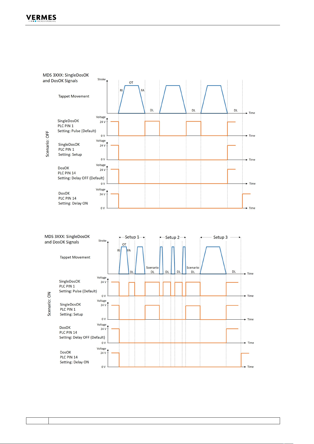
8.2.2.5 Comparison of the signals DosOK and SingleDosOK for Scenario ON and Scenario OFF
The following two figures show the signals DosOK and SingleDosOK in relation to the tappet
movement. In the first figure, scenarios are off, in the second figure, scenarios are ON.
Fig. 36: PLC signals with Scenario OFF
Fig. 37: PLC signals with Scenario ON
Communication Interfaces
VTK-TR-BA-171e-1 - User Manual MDS 3080-V
123
8.2.3 Remote Adjust
8.2.3.1 What is the Remote Adjust?
A remote adjust is similar to a normal adjust (see paragraph 6.5, page 52), but the system is
operated from a master device (e.g. a PC or an XY machine) by means of interfaces (PLC, RS-
232C). The function itself is identical.
Instead of the [enter]-key a short trigger signal is used and instead of the [esc]-key a long trigger
signal.
Short Trigger signal:
5 V or 24 V (PIN3 + PIN4 or PIN2 + PIN4 Input signal of MDC via 15 pin Sub-D)
Signal length: 500 μs – 80 ms
Long Trigger signal:
5 V or 24 V (PIN3 + PIN4 or PIN2 + PIN4 Input signal of MDC via 15 pin Sub-D)
Signal length: 110 ms – 200 ms
8.2.3.2 Advantages
The remote adjust allows for total control of a control unit integrated in a machine, since
dispensing parameters can be monitored by the software of this machine. The control unit can
be built in with permanent key lock. Thus, the modification of parameters without authorization
can be prevented in the machine software.
8.2.3.3 Procedure
The remote adjust has to be performed according to the following instructions:
IMPORTANT NOTE
Heating and remote adjust
In case your application uses a nozzle heater, you have to activate the heater before you start the
remote adjust. Make sure to wait long enough for the heater to reach stable temperature, since
the remote adjust could lead to an incorrect result otherwise.
Wear heat-resistant gloves while working with the valve!
INFORMATION
Displaying remote adjust
• In the course of the entire procedure, both adjust LEDs are lit simultaneously.
• The display shows “Remote Adjust is running!”
• For transmission of the orders between PC and control unit, both of the interfaces (RS-232C as
well as PLC-interface) are used.
• The parameters may not be in infinite mode.
• The baud rate of the serial interface should be set to 115200 or at least as high as possible.
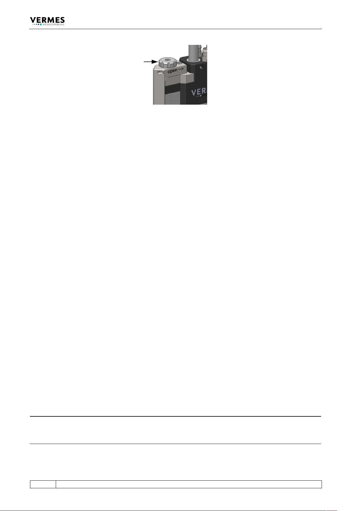
1. Preparation for the adjust: Use the tool MDT 327 to turn the adjust screw completely in the
direction “open” (see arrow on the valve, see Fig. 38, page 124, torque for screwing it open is
approx. 50 – 60 cN.m). Mount the tappet. Mount the complete fluid box and the nozzle
fixation nut. Screw the nozzle fixation nut absolutely tight by using the tool MDT 327 (torque
at least 150 cN.m).
Communication Interfaces
124
VTK-TR-BA-171e-1 - User Manual MDS 3080-V
Fig. 38: Screw open the adjust screw completely
2. Send the command “ADJUST:START” to the control unit via RS-232C. The system returns the
message “Release NU Attention fluid!!!!!“.
3. In order to confirm step 2, send a short trigger signal (500μs – 80 ms) to the control unit via
PLC interface.
4. The next message from the system is “Enter for 500 Shots”. Send a short trigger signal via PLC-
interface as confirmation.
5. The system then dispenses 500 shots, to clear the valve for the adjust. The next message
“Calibration Please Wait” appears. The calibration will take a few moments, before it is
finished. In case there is a problem with the calibration, the message “Adjust failed” appears.
6. If the calibration is successful and the valve is okay, move on to step 7. If the performance of
the valve is below 100 %, the message “max. Needle Lift = xx %” is returned. You should
exchange the valve and send it in for maintenance. Confirm the message with a short trigger
signal.
7. At first the message “Enter if Green” is send. This message is followed by the current adjust
value (e.g. -26 µm) and either:
1 (value too low, i.e. below 0 µm)
2 (value ok, i.e. between 0 µm and 4 µm)
3 (value too high, i.e. above 4 µm)
Adjust value and adjust answer are repeated in short intervals while you slowly screw the
adjust screw in the direction “close” by using the MDT 327, e.g.:
Enter if Green
-26 µm
1
-15 µm
1
0 µm
2
8. In order to confirm step 7, send a short trigger signal (500μs – 80 ms) to the control unit via
PLC-interface. This will only be accepted, if the value is okay. After the confirmation, the
system then returns the following response via RS-232C:
“Adjust LED Green”
The adjust has been completed successfully and the green LED is lit.
INFORMATION
Values out of range cannot be confirmed
Beyond the tolerance range of 0–4 µm (resp. 0–50 µm in fixed adjust mode) it is impossible to
confirm the values.