a3369b.pdf - 第130页
C ommunication Interfaces VTK - TR -BA- 171e - 1 - User Manua l MDS 3080 -V 121 8.2.2.3 External Mode Fig. 34 : Exter n al Mode 8.2.2.4 Infi nite Mode Fig. 35 : Infin ite Mo de
Communication Interfaces
120
VTK-TR-BA-171e-1 - User Manual MDS 3080-V
8.2.2 PLC-Signals
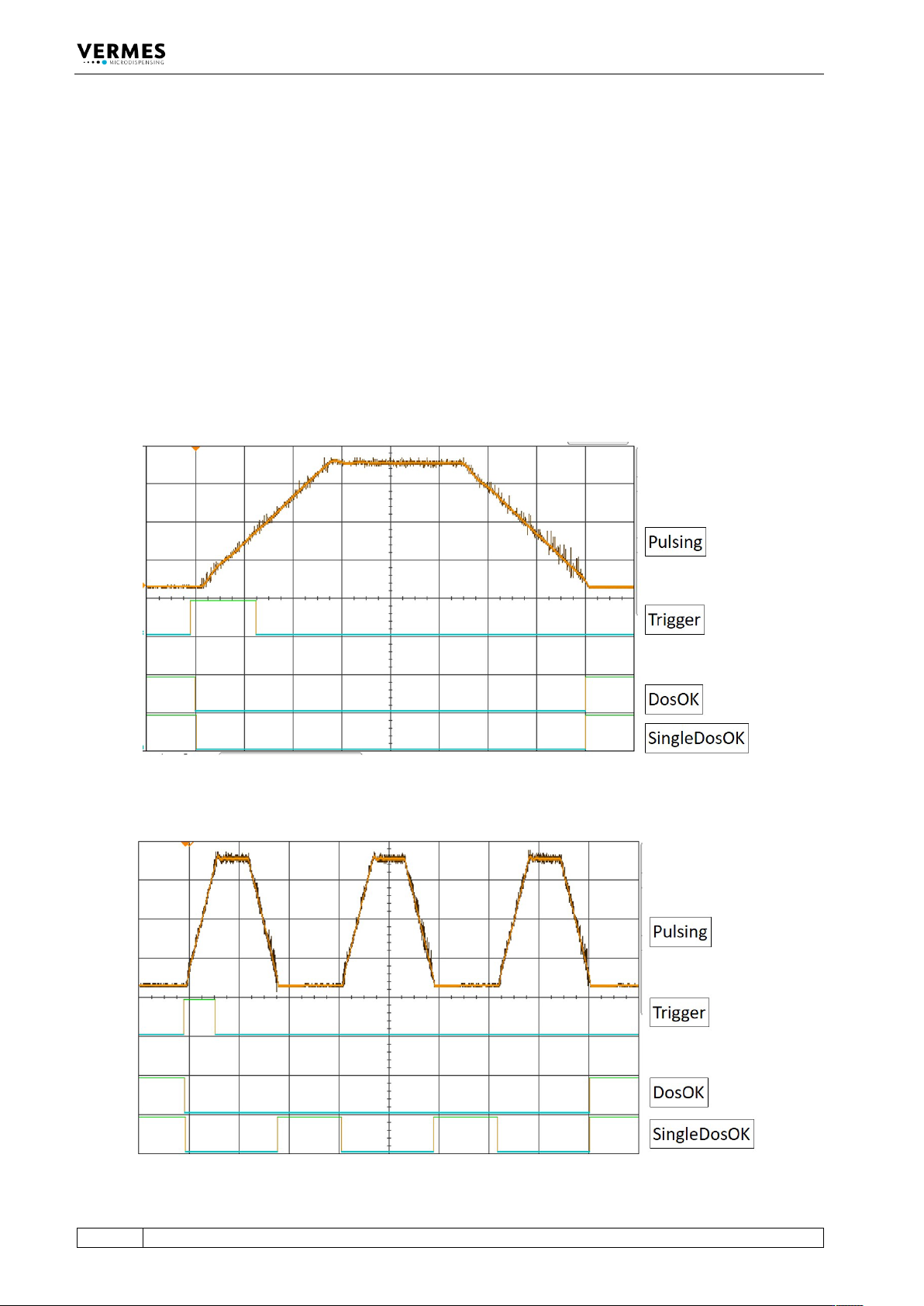
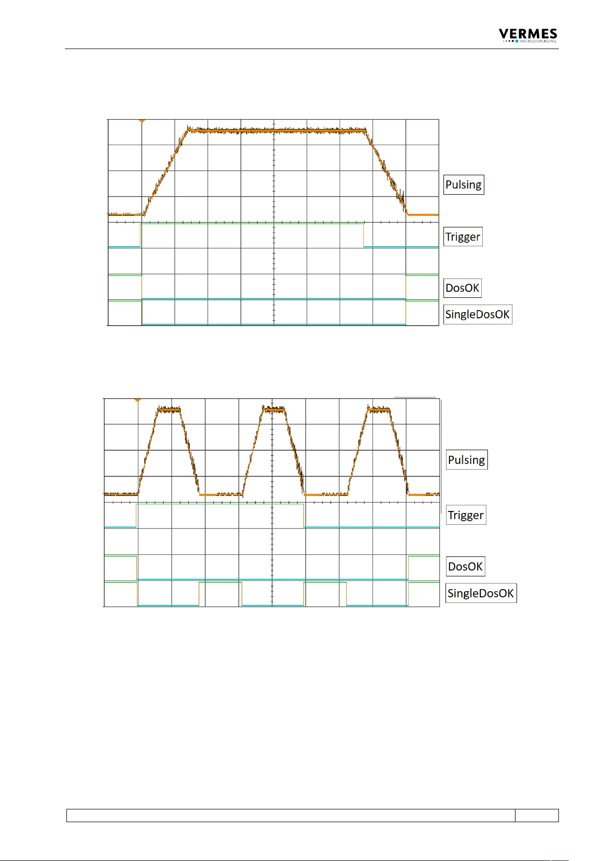
The following graphs show you the different PLC-signals Trigger, DosOK and SingleDosOK and
their behavior in various dispensing modes. The last paragraph then shows the effect of
scenarios. It also shows the differences for the variants of DosOK (Delay ON and Delay OFF) and
SingleDosOK (pulse and setup).
DosOK
The signal DosOK shows the length of a dispensing burst. During the pulsing burst, the signal is
“low”.
SingleDosOK
The signal SingleDosOK shows, that a single shot is being dispensed. When the signal changes to
“low”, a single shot is started. When the signal jumps back to “high”, it shows that the Open Time
has ended and the valve is closed.
8.2.2.1 Single-Shot Mode
Fig. 32: Single-Shot Mode
8.2.2.2 Burst Mode (Example with Three Shots)
Fig. 33: Burst Mode (Example with Three Shots)
Communication Interfaces
VTK-TR-BA-171e-1 - User Manual MDS 3080-V
121
8.2.2.3 External Mode
Fig. 34: External Mode
8.2.2.4 Infinite Mode
Fig. 35: Infinite Mode
Communication Interfaces
122
VTK-TR-BA-171e-1 - User Manual MDS 3080-V
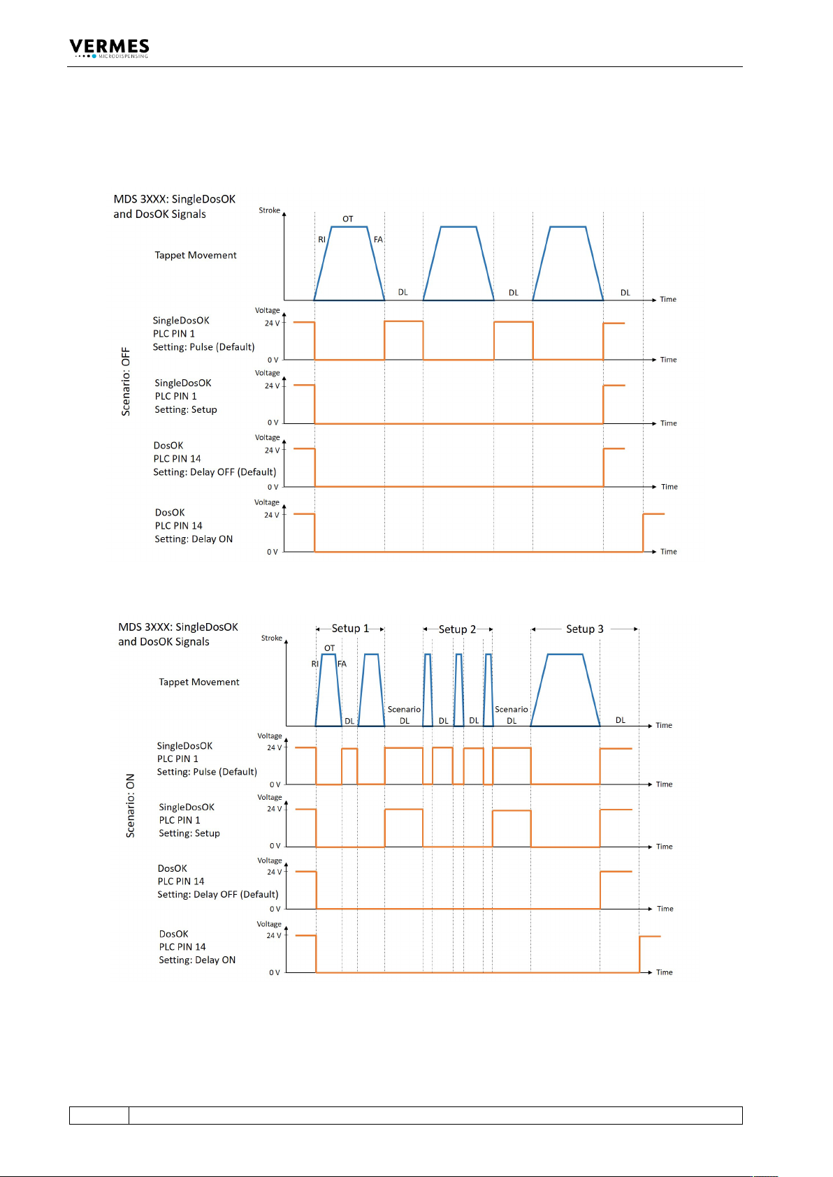
8.2.2.5 Comparison of the signals DosOK and SingleDosOK for Scenario ON and Scenario OFF
The following two figures show the signals DosOK and SingleDosOK in relation to the tappet
movement. In the first figure, scenarios are off, in the second figure, scenarios are ON.
Fig. 36: PLC signals with Scenario OFF
Fig. 37: PLC signals with Scenario ON