a3369b.pdf - 第128页
Communication Interfaces VTK - TR -BA- 171e - 1 - User Manua l MDS 3080 -V 119 8.2.1 Pin Fun ctio ns PIN Cha racter is tics Level Func tion 1 Outpu t 0 / +24 V , R a =2.2 k Ω (valid f or 0 V) Sing leDosOK 2 Input 0 / +24…
Communication Interfaces
118
VTK-TR-BA-171e-1 - User Manual MDS 3080-V
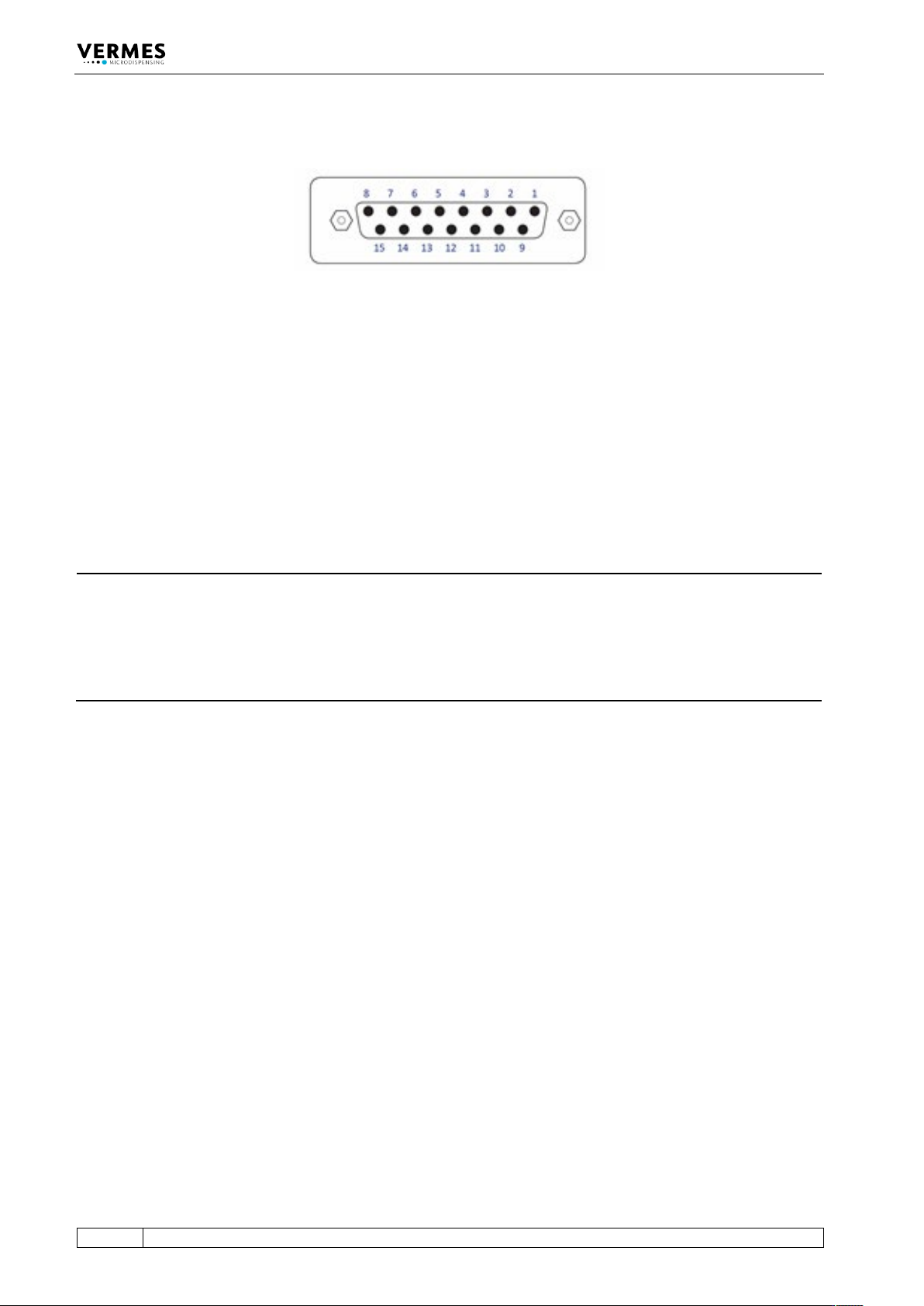
8.2 PLC-Interface: 15-pin, Sub-D
Fig. 31: PLC Interface: 15-pin, Sub-D
The PLC interface (illustrated above) works on digital basis without a particular syntax. It allows
for controlling a machine or device by means of a remote master device. Transmission of data is
possible in either direction. The trigger delay of this interface amounts to 96 μs.
Access is possible to:
• Status bits
• Values of voltage and current
• Set-Trigger signals initiating dispensing cycles (pulses) or complete packages of pulses
(bursts)
INFORMATION
Do not use keypad during PLC triggered dispensing
When a PLC-trigger is send, the keypad is locked at the same time. This lock can be lifted by
pressing the [enter]-key. But make sure not to do it during dispensing, since it also activates a
delay, which could affect your dispensing result. On the other hand, a trigger does not work, if
the MDC is not switched to the main menu. Additionally do not send a trigger, while the heater is
starting.
Communication Interfaces
VTK-TR-BA-171e-1 - User Manual MDS 3080-V
119
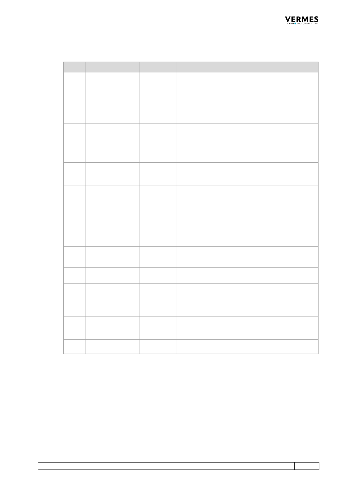
8.2.1 Pin Functions
PIN Characteristics Level Function
1
Output
0 / +24 V,
R
a
=2.2 kΩ
(valid for 0 V)
SingleDosOK
2
Input
0 / +24 V
R
i
=1.3 kΩ
Trigger Voltage Input
0 ... +5 V “Valve closed“
+12 V ... +30 V “Valve opened“
Positive edge triggering
3
Input
0/ +5 V
Ri
=400 Ω
Trigger Voltage Input
0 ... +0.8 V “Valve closed“
+3 V ... +5 V “Valve opened“
Positive edge triggering
4
Ground
___________
Ground
5
Output
0 / +24 V,
R
a
=2.2 kΩ
(valid for 0 V)
Set point Heating OK
6
Output
0 / +24 V,
R
a
=2.2 kΩ
(valid for 0 V)
Nozzle unit “adjusted” OK
(means green adjust LED)
7
Output
0 / +24 V,
R
a
=2.2 kΩ
(valid for 0 V)
Mains voltage OK
8
Output
0 … +5 V,
R
a
=20 kΩ
U-Needle – sensor signal (needle lift)
9
Output
24 V/50 mA
Power supply to external trigger
10
Ground
___________
Ground
11
Input
0 / 20 mA,
R
i
=500 Ω
Trigger Current Input
12
Reserved
___________
___________
13
Output
0 / +24 V,
R
a
=2.2 kΩ
(valid for 0 V)
For adjust: adjust failed. Nozzle unit screwed in too deep
or not enough.
Outside adjust: general error (24 V = error)
14
Output
0 / +24 V,
R
a
=2.2 kΩ
(valid for 0 V)
DosOK – Ready for dispensing (in the case of a pulse
package, at the end of the entire burst)
15
Input
___________
Trigger Abort, connection to ground, to interrupt
dispensing cycle
Communication Interfaces
120
VTK-TR-BA-171e-1 - User Manual MDS 3080-V
8.2.2 PLC-Signals
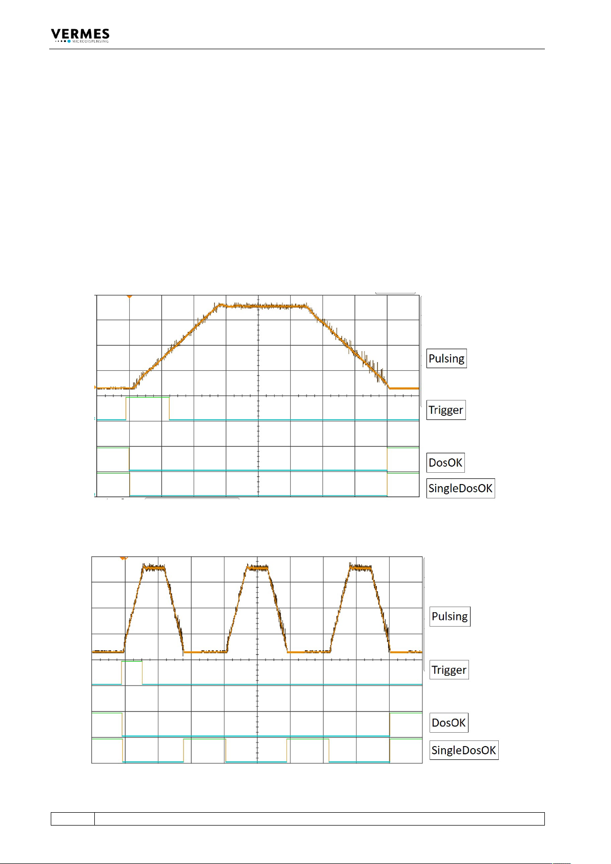
The following graphs show you the different PLC-signals Trigger, DosOK and SingleDosOK and
their behavior in various dispensing modes. The last paragraph then shows the effect of
scenarios. It also shows the differences for the variants of DosOK (Delay ON and Delay OFF) and
SingleDosOK (pulse and setup).
DosOK
The signal DosOK shows the length of a dispensing burst. During the pulsing burst, the signal is
“low”.
SingleDosOK
The signal SingleDosOK shows, that a single shot is being dispensed. When the signal changes to
“low”, a single shot is started. When the signal jumps back to “high”, it shows that the Open Time
has ended and the valve is closed.
8.2.2.1 Single-Shot Mode
Fig. 32: Single-Shot Mode
8.2.2.2 Burst Mode (Example with Three Shots)
Fig. 33: Burst Mode (Example with Three Shots)