a3369b.pdf - 第59页
Initial Operation 50 VTK - TR -BA- 171e - 1 - User Man u al MDS 3080 -V Fig. 21 : Connect or sensor cable - gri p 6.3.3.3 Mains Cable P ower t o the con trol uni t is supplied b y the black main s cable . IMPORTANT NOTE …
Initial Operation
VTK-TR-BA-171e-1 - User Manual MDS 3080-V
49
6.3.3.2 Sensor Cable
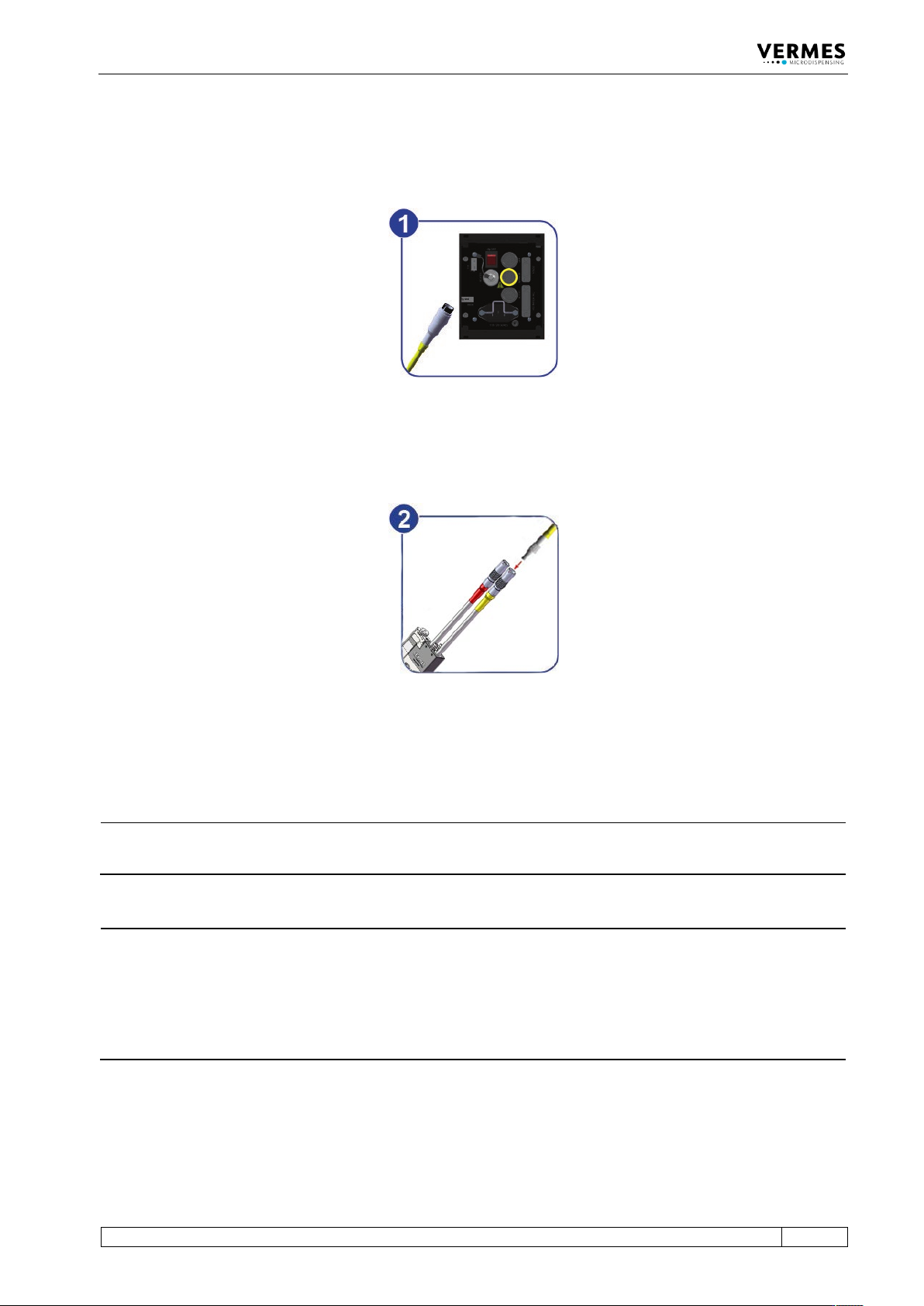
This cable wrapped in yellow is provided to transfer data from the sensor integrated in the valve
to the control unit. Connect it as described below.
Fig. 19: Connecting the sensor cable – step 1
– Step 1: First, fix the sensor cable to the corresponding socket on the rear side of the control
unit.
Fig. 20: Connecting the sensor cable – step 2
– Step 2: The five-pin connector with a corrugated sleeve has to be connected to the yellow
marked, looped cable attached to the valve.
INFORMATION
Connecting cables
Verify during the connecting procedure that the red dots on the plugs point towards each other.
INFORMATION
Release latch for disconnection
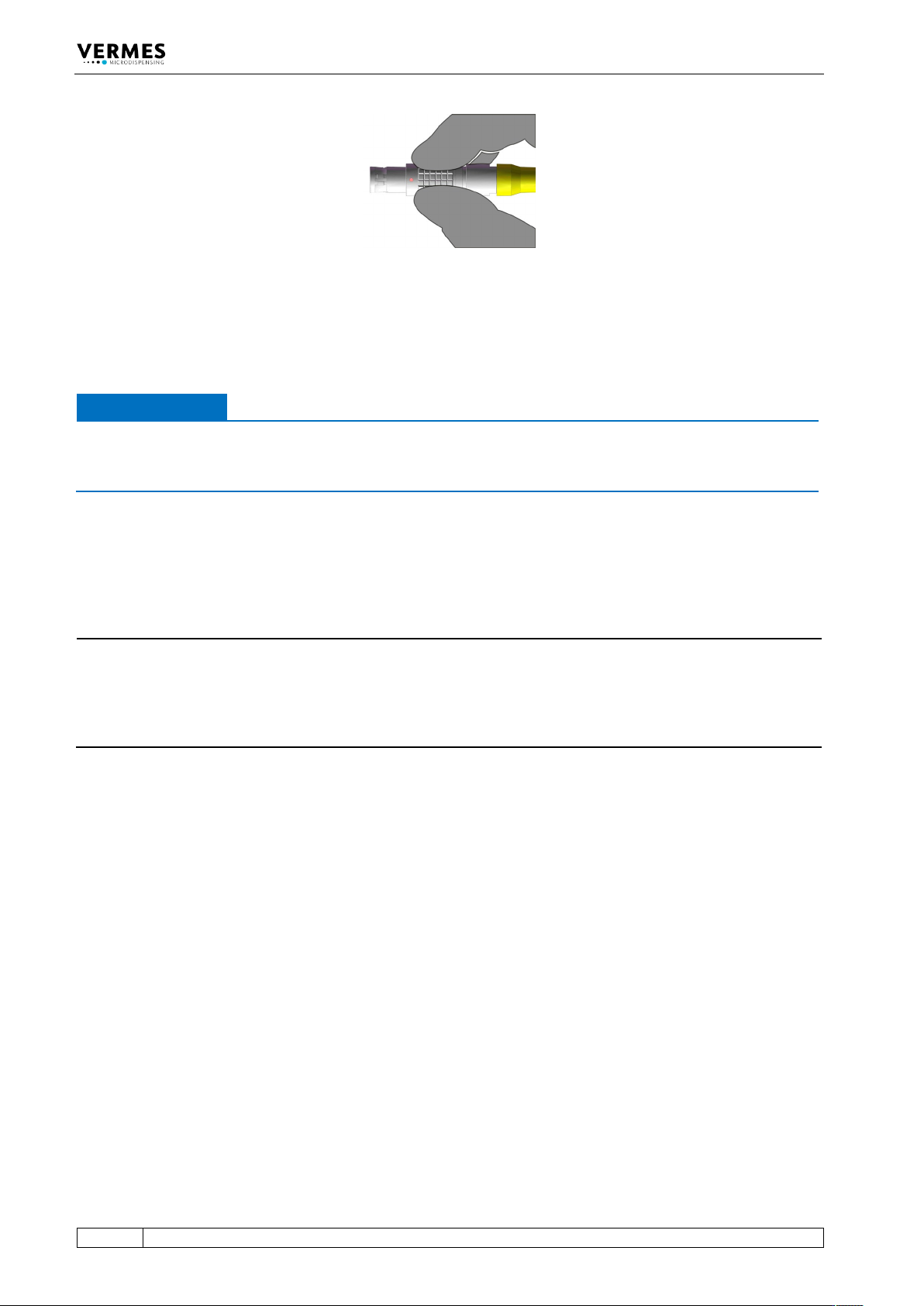
To secure the connectors there is a latch, which you have to release before disconnection. You
have to grip the corrugated outhousing. Pull back the outhousing of the male connector to
release the latch (see Fig. 21, page 50). Then pull both connectors apart without losing the grip
and they will separate.
Do not pull at the cables!
Initial Operation
50
VTK-TR-BA-171e-1 - User Manual MDS 3080-V
Fig. 21: Connector sensor cable - grip
6.3.3.3 Mains Cable
Power to the control unit is supplied by the black mains cable.
IMPORTANT NOTE
Type plate
Do not connect the system to the mains, before having checked the type plate of the model you
want to install (mains voltage, 110 V AC or 230 V AC).
– Step 1: Plug the cable into the socket at the bottom of the rear side of the control unit.
– Step 2: Connect the cable to the power supply.
– Step 3: Press the ON/OFF button, located on the rear side of the control unit.
INFORMATION
Valve not connected
If the valve is not connected, an error message (“199 Valve Error – Escape for Auxi.“) appears on
the screen. Switch OFF the system, disconnect it from the mains and complete the installation
before continuing. Alternatively, you can press the [ESC]-key. When confirming it with [Enter],
you change into the Auxiliary Mode (see paragraph 7.13, page 76).
Initial Operation
VTK-TR-BA-171e-1 - User Manual MDS 3080-V
51
6.4 Valves with Air cooling
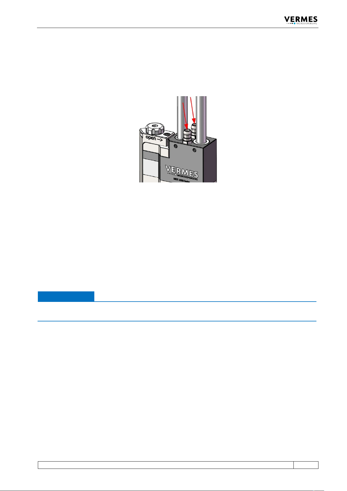
If you want to air cool your valve with compressed air, you have to connect the air hoses to the
compressed air supply after finishing the cable connections of the valve. Use hoses with an inner
diameter of 4 mm.
Abb. 22: Valve with air-cooling adapters
The air-cooling adapters are equal. Therefore, it does not matter which one you use as inlet, and
which one as outlet. Push end of the hose onto the air inlet of the valve you chose. Connect the
other end of the hose to the air supply.
The second connector represents the outlet, evacuating the heated compressed air from the
valve. Push one end of the hose onto the connector. When running the hose away from the
valve, take care not to impair functions of the system, or to disturb operators during their work.
For air-cooling, you should use a compressed-air pressure of about 2 bar. For a high temperature
application, you should set the pressure higher, at up to 4 bar.
IMPORTANT NOTE
Quality of compressed air
Quality of compressed air should comply with DIN ISO 8573-1.
The pneumatic supply used for cooling of the valve should be free of fine dust and condensate
and correspond to classes 1, 4, 2 according to DIN/ISO 8573-1.
• Solid particles: max. particle number/m³: 0.1 – 0.5 µm: < 20000, 0.5 – 1 µm: < 400, 1 – 5 µm: <
10 = Quality class 1
• Water content: max. pressure dew point +3°C = Quality class 4
• Residual oil: max. 0.1mg/m³ = Quality class 2