a3369b.pdf - 第43页
Control Unit MDC 34 VTK - TR -BA- 171e - 1 - User Man u al MDS 3080 -V 4.6 Memories of the MDC The MDC contains sever al memori es to sav e paramet er setups. The fi rs t one i s the RA M (Random A ccess Mem ory). Here t…
Control Unit MDC
VTK-TR-BA-171e-1 - User Manual MDS 3080-V
33
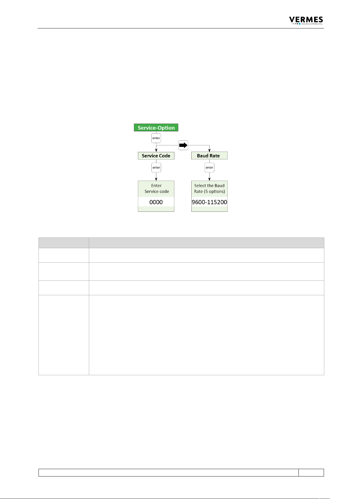
4.5.6 Submenu “Service-Option”
This menu has two sections. In “Service Code”, you can enter a service code. If you enter 2030,
you switch ON/OFF the valve check during start-up of the MDC. If you enter 1100, you can switch
ON/OFF the control lamps for adjust (see paragraph 4.2 "Front Side", page 21). If you enter 1000,
you enter a further submenu containing the options listed in the table below.
“Baud Rate” is used to change the baud rate. There are five possible values: 9600, 19200, 38400,
57600 and 115200 (new MDCs are set to 9600).
Fig. 10: Submenu „Service-Option“
Option Explanation
SingleDosOK
You can select between the possibilities that the SingleDosOK signal is switched per pulse or
per setup. (For the pin configuration of the PLC inter-face, see paragraph 8.2.1, page 119.)
DosOK with
Delay
You can select, if before switching the signal DosOK there should be one delay executed at
the end.
Auxiliary Mode
Here the auxiliary mode can be switched ON or OFF (see paragraph 7.13 "Auxiliary Mode",
page 76).
Factory Settings
Here any parameters can be returned to the default factory settings (see paragraph 7.10
"Factory Settings", page 69). You have got four alternatives:
• Setup 0 – 3 (the parameters of the working configuration and the setups 1 to 3 are
returned to the factory settings)
• Reset ALL (all parameters are returned, including the settings of the scenarios; also the
heater will be turned OFF and the temperature set to 1°C)
• Scenario (the parameters and settings of the scenarios are returned to the factory
settings)
• Setup ALL (the parameters of the working configuration and all setups are returned,
setups 4 – 10 receive values of setup 0)

Control Unit MDC
34
VTK-TR-BA-171e-1 - User Manual MDS 3080-V
4.6 Memories of the MDC
The MDC contains several memories to save parameter setups.
The first one is the RAM (Random Access Memory). Here the parameters of the current dispense
process will be saved. This memory will be erased when the controller is switched of or
disconnected from power. When starting again, the MDC will load the first of eleven parameter
memory sets saved on the EEPROM (Electrically Erasable Programmable Read Only Memory) into
the RAM. This first parameter setup is also called the “EEPROM current working parameter
configuration”, or short “working configuration” or “EEPROM working configuration”.
The parameter set in the EEPROM working configuration is usually the same as the parameter set
saved in the RAM memory. When using the keypad to program the controller, the two memories
will always have the same contents. The only way to create a difference in the parameter set
saved in the RAM and in the EEPROM working configuration is by using some special commands
through the RS-232C.
The remaining ten EEPROM memory sets can be used to save different parameter setups when
programming the controller through the keypad interface (use the command [Save]).
In order to change the values saved in the EEPROM working configuration you may use the MDC
keypad (enter the parameters in the menu “Pulse Parameters”, then press [Enter]).
Alternatively, you may use one of the following commands via RS-232C:
• TRIGGER:SET:<Rising>,<Open Time>,<Falling>,<Needle Lift>,<Number of Pulses>,<Delay>,1
• TRIGGER:ASET:<Rising>,<Open Time>,<Falling>,<Needle Lift>,<Number of Pulses>,<Delay>,1
• STRIGGER:SET:<Rising>,<Open Time>,<Falling>,<Needle Lift>,<Number of Pulses>,<Delay>,1
• STRIGGER:ASET:<Rising>,<Open Time>,<Falling>,<Needle Lift>,<Number of Pulses>,<Delay>,1
All values transmitted to the control unit by one of the following four commands will not be
saved in the EEPROM working configuration.
• TRIGGER:SET:<Rising>,<Open Time>,<Falling>,<Needle Lift>,<Number of Pulses>,<Delay>
• TRIGGER:ASET:<Rising>,<Open Time>,<Falling>,<Needle Lift>,<Number of Pulses>,<Delay>
• STRIGGER:SET:<Rising>,<Open Time>,<Falling>,<Needle Lift>,<Number of Pulses>,<Delay>
• STRIGGER:ASET:<Rising>,<Open Time>,<Falling>,<Needle Lift>,<Number of Pulses>,<Delay>
Instead, it will remain in the RAM memory until erased by another RS-232C command, or when
the control unit is switched OFF and the EEPROM is read out into the RAM during restart. The
reason for having these two different types of commands (the distinction is the “1” at the end) is
that it takes up to 1 sec to save the parameter set in the EEPROM.
On top of the working configuration and the ten parameter setups, there is another parameter
setting saved in the software on the EEPROM. This is called the “factory setting”. You cannot
change it. It may be loaded to the working configuration and the RAM memory after major
disturbances of the system.
Additionally, there is the possibility to save combinations of setups, so called “Scenarios” (see
paragraph 7.9 "Scenarios", page 66).
Microdispensing Valve
VTK-TR-BA-171e-1 - User Manual MDS 3080-V
35
5 Microdispensing Valve
This chapter contains relevant information about the valve. It describes the structure and the
hardware configuration.
5.1 Composition of the Valve
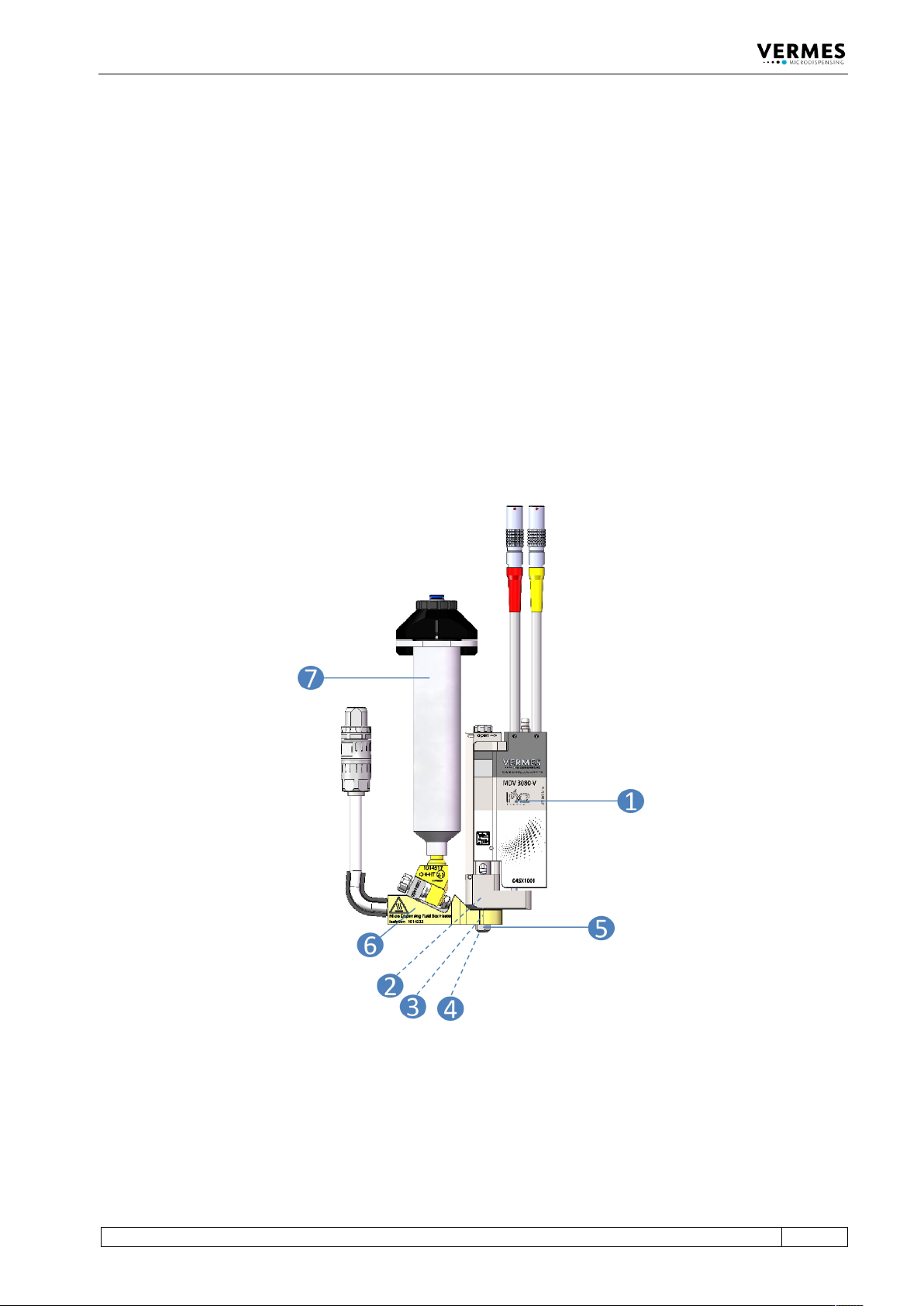
The Microdispensing valves of Vermes Microdispensing are modular. A valve is composed of
seven different modules:
• Valve body (includes Electronics module and Actuator system) (1)
• Tappet (not visible) (2)
• Tappet sealing (not visible) (3)
• Nozzle insert (not visible) (4)
• Nozzle fixation nut (5)
• Fluid box (6)
• Media supply (7)
Fig. 11: Composition
The valve body (1) accommodates the electronics module, the actuator system and the adjust
screw. The electronics module holds the electronics to receive the actuator and sensor signals.
Here are the connectors for sensor cable and actuator cable integrated in the surface of the case;
they have to be linked to the control unit. The electronics module is connected to the actuator
system, representing the core of the microdispensing valve. The actuator system houses the