a3369b.pdf - 第91页
Communicatio n In terface s 82 VTK - TR -BA- 171e - 1 - User Man u al MDS 3080 -V 8 Communi cati on In terf aces The control uni t has t hree co mmun i cation in terfac es. Th ere is a 9 - pin serial interface , RS - 232…

Operation
VTK-TR-BA-171e-1 - User Manual MDS 3080-V
81
7.15 Switching OFF the Microdispensing System
– Step 1: The current dispensing cycle must be completed, so that the valve is in home position.
– Step 2: Lower the supply pressure to atmospheric pressure (because in initial position, the
valve is still opened). Disengage the pneumatic supply. If required, close the cartridge by
using locking pin MDT 309.
– Step 3: Switch OFF the control unit (ON/OFF button at the rear end). After switching OFF the
control unit, please wait a few seconds.
– Step 4: Disconnect the valve from fluid supply.
– Step 5: Remove all cables from the valve.
– Step 6: Unscrew the screws used for fixing the valve in place.
After working with self-curing substances, immediate cleaning is advisable in order to avoid
clogging. This concerns the valve itself and all parts in contact with the fluid. The valve and its
subcomponents have to be dismantled and cleaned (see chapter 9, page 129).
Communication Interfaces
82
VTK-TR-BA-171e-1 - User Manual MDS 3080-V
8 Communication Interfaces
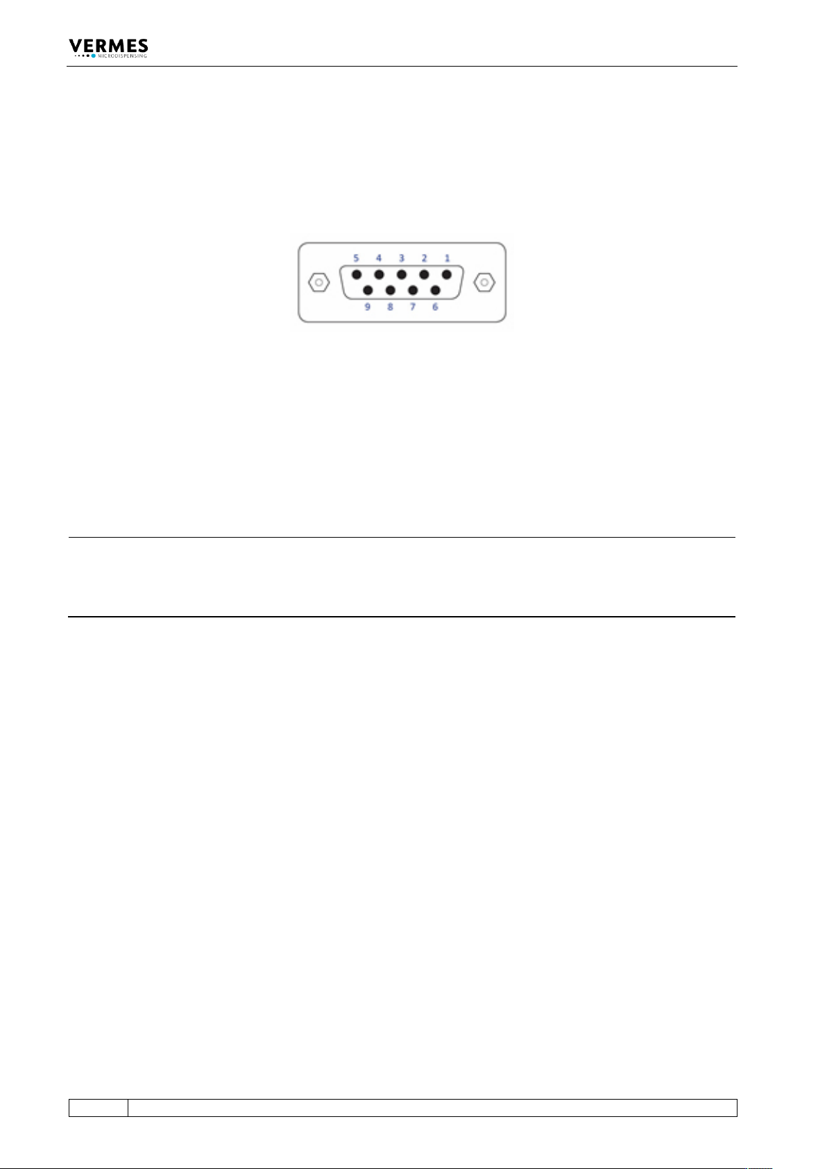
The control unit has three communication interfaces. There is a 9-pin serial interface, RS-232C, a
15-pin PLC-interface and an AUX socket.
8.1 Serial Interface RS-232C: 9-Pin Sub-D
Fig. 30: Serial interface
The local interface is structured according to SCPI Standard.
These “Standard Commands for Programmable Instruments” represent a standardized set of
instructions used for control and programming, transmitted in form of ASCII text. They can be
generated by any selectable programming language in any environment. The serial interface
operates by means of software handshake. The hardware handshake communications are not in
use.
INFORMATION
Communication while triggering
Do not send instructions through this interface in the course of a running dispensing cycle.
Communication is only possible between distinct sequences (signal DosOK on “high”). This is
especially important during start-up of a heater.
After sending data or parameters to the control unit, you have to wait for the “OK” signal before
you can start further actions. You only can send data while the MDC is in the main menu.
Communication Interfaces
VTK-TR-BA-171e-1 - User Manual MDS 3080-V
83
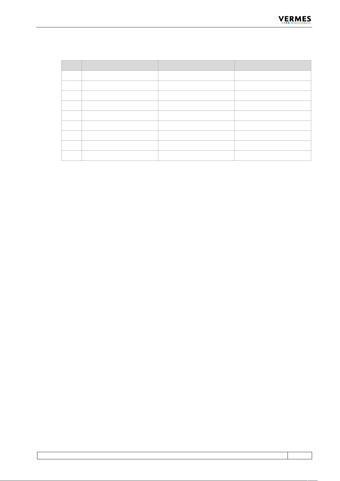
8.1.1 Pin Functions
PIN Characteristics Level Function
1 Reserved ___________ ___________
2
Output
TX
Serial transmission signal
3
Input
RX
Serial reception signal
4
Connected to PIN 6
5
Ground
Ground
6
Connected to PIN 4
7
Reserved
___________
___________
8
Reserved
___________
___________
9
Reserved
___________
___________
The RS-232C log of the control unit uses RS-232C standard and is designed for communication
via a serial cable, connected 1:1, with a Sub-D nine pin connector.
The following parameter configuration is used for the communication with the control unit:
• Synchronous mode: Half-duplex
• Bits/s: 9600 – 115200 (5 different options available, see paragraph 4.5.6, page 33)
• Start bit: 1
• String length: 8 bit (ASCII)
• Parity: None
• Stop bit: 1
• Log: None