a3369b.pdf - 第98页
Communication Interfaces VTK - TR -BA- 171e - 1 - User Manua l MDS 3080 -V 89 5 ADJUST :? Descript ion: This command is used to verif y the success of t he adjust . The resu lt cons ist s in one of t he following op tion…
Communication Interfaces
88
VTK-TR-BA-171e-1 - User Manual MDS 3080-V
8.1.2.2 Explanations
0
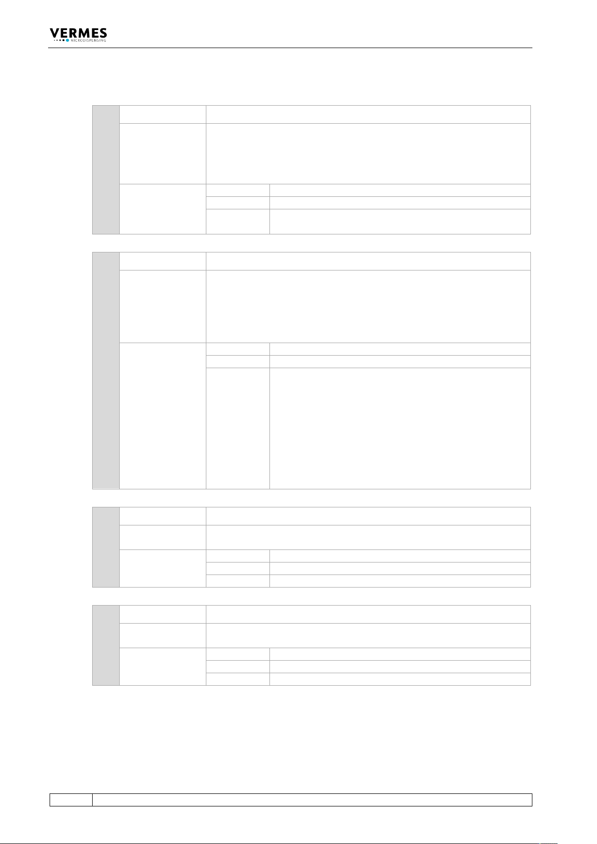
1 *ESR? ESR? = Event Status Register Query
Description:
This command shows the latest error codes created by the system, starting
with the latest event. At the most 50 error messages will be shown.
Each error messages also includes the valve ID (if known) and a time and
date stamp. If the RTC of the MDC is defect, the value will be given as
“00:00:00 2014-01-01”.
Example:
Input:
*ESR?
Result:
List of the (up to 50) latest error messages
Return:
8 199 VALVE ERROR 08FU04 09:16:38 2018-01-21
9 104 INCORR. VALVE 08FU04 09:16:21 2018-01-21
2 *ESR2? ESR2? = Event Status Register Query 2
Description:
This command shows the latest error codes created by the system, starting
with the latest event. There will be shown a max of 50 error messages.
Each error messages also includes the valve ID (if known) and a time and
date stamp. If the RTC of the MDC is defect, the value will be given as
“00:00:00 2014-01-01”. Additionally the parameters of setups 0 to 3 before
the error are listed.
Example:
Input:
*ESR2?
Result:
List of the (up to 50) latest error messages with parameters
Return:
20 199 VALVE ERROR 000000 09:16:38 2018-01-21
0, 0, 0, 0, 0, 0
0, 0, 0, 0, 0, 0
0, 0, 0, 0, 0, 0
0, 0, 0, 0, 0, 0
27 104 INCORR. VALVE 08FU04 09:16:21 2018-01-21
30, 5, 30, 80, 1, 20
50, 20, 20, 80, 1, 100
50, 20, 20, 80, 1, 100
50, 20, 20, 80, 1, 100
3 *IDN? IDN? = Identification Query
Description:
Device specific information, formatted as follows: type (hv, or lv), software
version. Important for contact with our Technical Support.
Example:
Input:
*IDN?
Result:
Micro Dispenser LV, 4071LU1-D
Return:
Micro Dispenser LV, 4071LU1-D
4 *OPC? OPC? = Operation Complete Query
Description:
Monitoring the last trigger impulses. After this, the counter is cleared to
zero.
Example:
Input:
*OPC?
Result:
Number of the last pulses. Clears the counter to zero.
Return:
6699
Communication Interfaces
VTK-TR-BA-171e-1 - User Manual MDS 3080-V
89
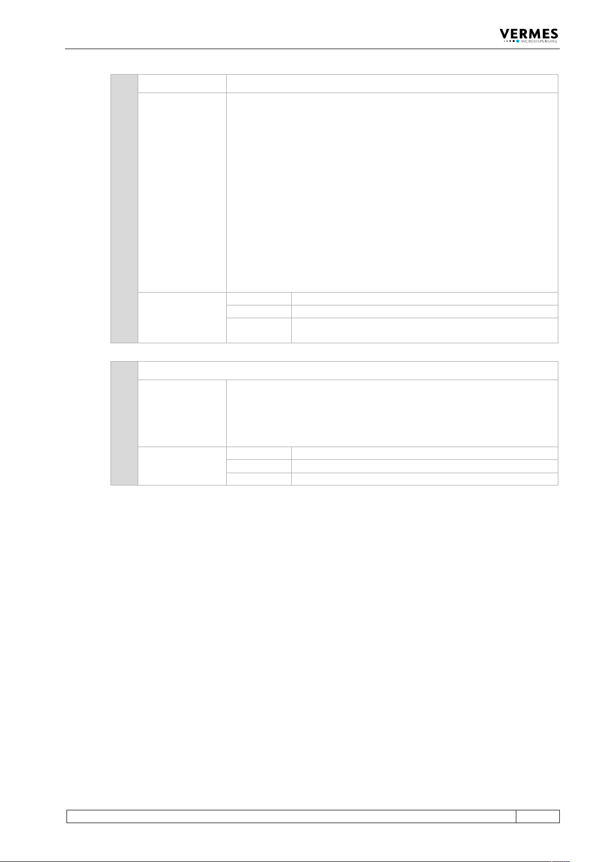
5 ADJUST:?
Description:
This command is used to verify the success of the adjust.
The result consists in one of the following options:
• Unknown state (Result: 0)
The system is not able to interpret the question and has to be switched
OFF and ON again. The adjust must be repeated. This event however is
an exception.
• The nozzle unit is too far down (Result: 1)
You have to screw the adjust screw in the direction “Close”. An adjust is
required (or must be repeated).
• The adjust was successful (Result: 2)
The position of the nozzle insert relatively to the tappet is OK.
• The nozzle unit is too far up (Result: 3)
You have to screw the adjust screw in the direction “Open”. The adjust
must be performed (or repeated).
Example:
Input:
ADJUST:?
Result:
The system informs about the current nozzle position.
Return:
2
The nozzle is correctly adjusted. Adjust was successful.
6 ADJUST:START
Description:
Sending this command causes the adjust to be executed at once. This
procedure checks on the position of the nozzle insert with respect to the
tappet. It is required during each initial start-up and after replacing the
nozzle unit.
For further information read paragraph 8.2.3, page 123.
Example:
Input:
ADJUST:START
Result:
The adjust is initiated.
Return:
Release NU Attention Fluid!!!!!
Communication Interfaces
90
VTK-TR-BA-171e-1 - User Manual MDS 3080-V
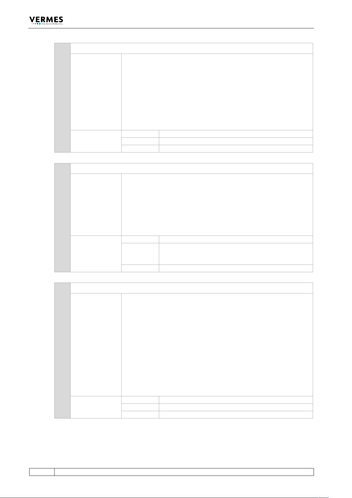
7 ADJUST:TO:CHANGE:<adjust range>
Description:
This command changes the size of the adjust range, where you can confirm
an adjust. The value entered is ten times the value in micrometers. E.g.
entering 142 will set the adjust range to 14.2 µm.
You can only enter values between 58 and 300 (i.e. 5.8 µm and 30.0 µm).
For further information read paragraph 14.8, page 174.
Important Note!
Widening the range too much can lead to a valve leaking even after the
adjust. Use the command carefully. It is mostly meant for applications
which use the fixed adjust.
Example:
Input:
ADJUST:TO:CHANGE:142
Result:
The adjust range is set to 14.2 µm.
Return:
OK
8 ADJUST:VAL:FA:?
Description:
This command gives you the status of the fixed adjust. The two parameters
have the following meaning.
• Fixed adjust activated? (0 = FA off, 1 = FA on)
• Has valve been adjusted with a fixed adjust (0 = not
adjusted with fixed adjust, 1 = adjusted with fixed
adjust)
For further information read paragraph 7.12, page 76.
Example:
Input:
ADJUST:VAL:FA?
Result:
The command gives you the status of the fixed adjust (here:
fixed adjust is activated and the last adjust with this valve
has been performed as a fixed adjust).
Return:
1,1
9 ADJ:VALUES:?
Description:
This command gives you the parameters for the adjust range, where you
can confirm the adjust. The five parameters have the following meaning.
• Setting in regards to FA/FD (0 = normal, 1 = FA, 2 =
FA + FD, 3 = FD)
• Adjust values in µm (range 0 – 4 for normal adjust, 0 –
50 for fixed adjust, set during the adjust)
• Deviation from the adjust value in µm * 10 (e.g. 23 =
deviation by 2.3 µm)
• Range where the green adjust LED is ON in µm * 10
(e.g. 82 = 8.2 * 10, meaning a range from +/- 4.1 µm)
• LED status (1 = OFF, 2 = green, 3 = red)
For further information read paragraph 14.8, page 174.
Example:
Input:
ADJ:VALUES:?
Result:
The command gives you the adjust parameters.
Return:
2,45,23,142,2