a3369b.pdf - 第77页
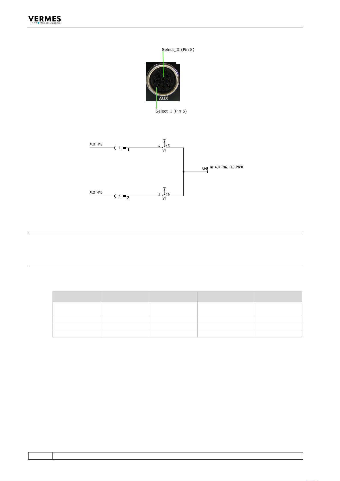
Operation 68 VTK - TR -BA- 171e - 1 - User Man u al MDS 3080 -V Fig . 28 : Select Pins Fig. 29 : Schem atic of usag e of select pins INFORMATION Sele ct pin s with other co mman ds Select p ins wi ll be chec ked for trig…

Operation
VTK-TR-BA-171e-1 - User Manual MDS 3080-V
67
“OFF”, the trigger only affects a segment on “infinite” number of pulses. In that case, once the
trigger is switched to “low”, the system moves on to the scenario delay, followed by any
segments still to come. Unlike the “ON” situation, the scenario does not end immediately.
Scenarios can be controlled in two ways:
• via keypad (see next part)
• with remote commands via the serial interface RS-232C (see paragraph 8.1, page 82)
Scenarios can also be controlled directly via select pins (see paragraph 7.8, page 64). You have to
set item “Scenario” of the submenu “Scenario” to “ON“. While this is the case, the display shows
“Scenario” where it usually shows the frequency.
7.9.2 Entering Scenarios
To enter the parameters for a scenario you have to go to the submenu “Scenario” (see
paragraph 4.5.5, page 31). To do so, you have to press [enter] in the main menu and then [←]
twice. Confirm with [enter] to reach the item “Scenario”. Press [enter] and use either [↑] or [↓] to
switch between “ON” and “OFF”. Select “ON” and confirm your choice with [enter].
Now you can select the desired scenario with [→] (also paragraph 4.5.5, page 31, the diagram for
the submenu “Scenario-Def”). Press [enter]. Enter the first setup (“0”, “1”, “2”, “3” or “-”) and
confirm with [enter]. With [→] you reach “ScNP”, where you can enter the Number of Pulses. For
the scenario, this value will replace the one saved within the setup. Values can be between 1 and
32,000 or “infinite”. Confirm with [enter]. With another [→] you reach “ScDL”, where you can set
the scenario delay. Afterwards confirm with [enter].
Repeat with the second segment, and so on, until you have entered all segments you need or
until you reached the maximum of ten defined segments. When you want to end the chain, enter
“-” instead of the number of a setup. No further segment will be shown in the menu. If you
replace a “-” on a given segment with a correct number, it is unlocked. The system starts with the
setup NP and 10 ms as Scenario-Delay, but you can change these values individually.
With [→] after the last segment you reach “PLCStop” (Scenario-PLC-Stop). After pressing [enter]
you can switch between “ON” and “OFF” (using any arrow key). Confirm your choice with [enter].
(If PLCStop is your only goal in this submenu, it is faster to click [←] once on this level. Like all
other menus, this is “wrap-around”.)
This process you have to repeat for each of the up to four scenarios you want to define.
Scenarios are started with a trigger event. This can be a trigger via keypad, a PLC interrupt or the
“Valve Open” command (without parameters) via the serial interface.
INFORMATION
When no scenario is triggered
Valve-Up/-Down via serial interface and the [F1] key cannot trigger a scenario.
7.9.3 Scenario Selection with Select Pins
Scenarios can be directly controlled via the select pins of the AUX socket (see Fig. 28, page 68), if
“Scenario” in the submenu “Scenario” is turned “ON”. If that is not the case, they switch between
the setups 0 to 3 instead.
With the pins Select_I (AUX socket Pin 5) and Select_II (AUX socket Pin 8) it is possible to switch
rapidly between different sets of parameters. In their blank state, the select pins are on a high
level (pull-ups to 24 V). You have to switch one or both to low (Gnd) to select a different setup
(see Tab. 22, page 68). You have to switch them before triggering.
Operation
68
VTK-TR-BA-171e-1 - User Manual MDS 3080-V
Fig. 28: Select Pins
Fig. 29: Schematic of usage of select pins
INFORMATION
Select pins with other commands
Select pins will be checked for triggering via PLC interface, for the serial commands VALVE:OPEN,
VALVE:AOPEN, SVALVE:OPEN and SVALVE:AOPEN (in the versions without parameters) and when
pressing the key [trig].
You can also simulate the select pin settings for these four commands by using the command
extensions “S0”, “S1”, “S2” or “S3” (see paragraph 8.1.2.2 "Explanations", page 88).
Parameters Select1 Select2 Scenario „OFF“ Scenario „ON“
S0
High
High
Setup 0 (working
configuration)
Scenario 1
S1
Low
High
Setup 1
Scenario 2
S2
High
Low
Setup 2
Scenario 3
S3
Low
Low
Setup 3
Scenario 4
Tab. 22: Select Pin settings
Operation
VTK-TR-BA-171e-1 - User Manual MDS 3080-V
69
7.10 Factory Settings
By recalling the factory settings (implemented by the manufacturer), you return to a predefined
starting position. This is useful to start the input of a new parameter set.
These are the values contained in the factory settings:
RI = 0.50 ms, FA = 0.50 ms, OT = 2.0 ms, NL = 70 %, DL = 10.0 ms and NP = 1.
– Step 1: Press [recall].
– Step 2: [↓] immediately opens this parameter set.
– Step 3: Confirm the selection with [enter].
INFORMATION
Aborting the process
The working configuration (setup 0) is changed to the factory settings. Press [esc] to abort at any
time.
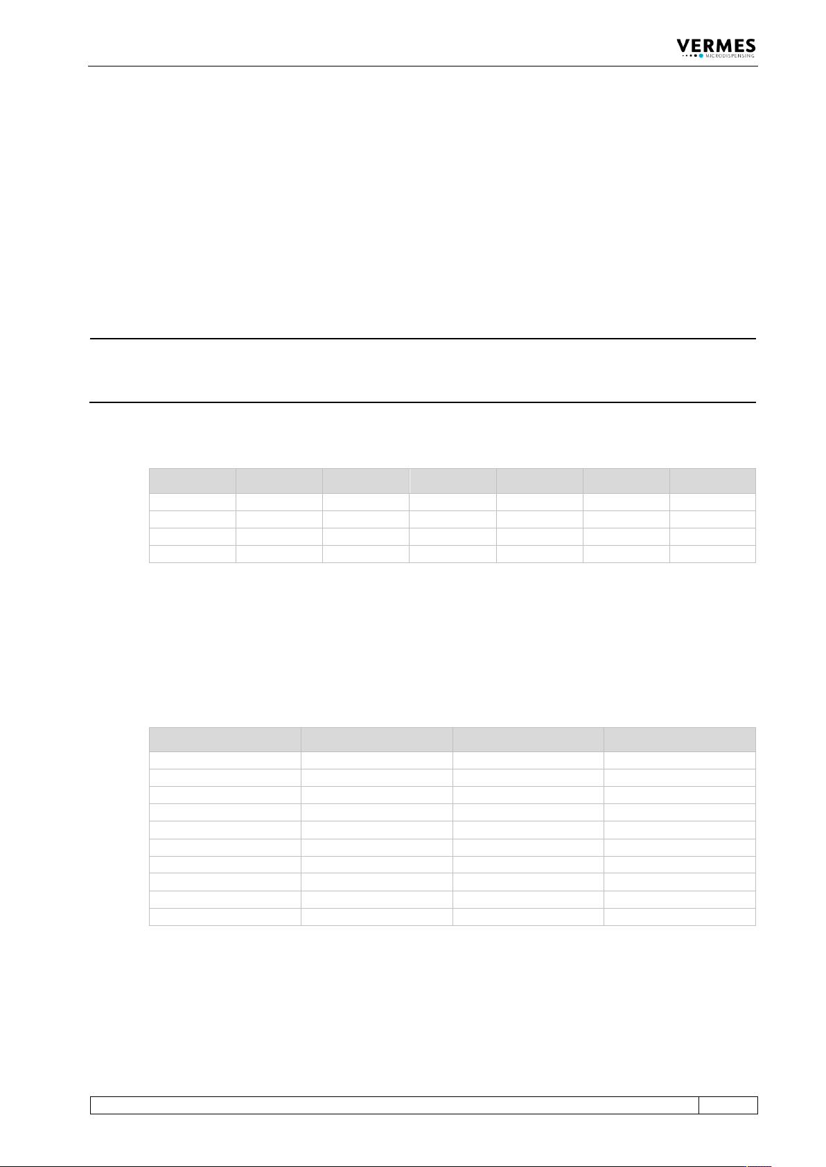
The following table lists the factory settings of the setups.
RI [ms] OT [ms] FA [ms] NL [%] NP DL [ms]
Setup 0
0.50
2.0
0.5
70
1
10.0
Setup 1
10.0
4.0
1.4
70
1
10.0
Setup 2
5.0
2.0
2.0
70
10
10.0
Setup 3
4.0
0.6
1.6
70
1
10.0
Tab. 23: Factory settings of the setups
With Setup ALL (see paragraph 4.5.6 "Submenu “Service-Option”", page 33) Setup 4 – 10 get the
same values as setup 0 (working configuration).
The factory settings for all four scenarios are the same. The PLCStop is “OFF”, the other
parameters are shown in the following table.
Sc.-Segment Setup used ScNP Sc.-Delay
Segment 1
0
as setup NP
10.0 ms
Segment 2
1
as setup NP
10.0 ms
Segment 3
2
as setup NP
10.0 ms
Segment 4
3
as setup NP
10.0 ms
Segment 5
0
as setup NP
10.0 ms
Segment 6
1
as setup NP
10.0 ms
Segment 7
2
as setup NP
10.0 ms
Segment 8
3
as setup NP
10.0 ms
Segment 9
0
as setup NP
10.0 ms
Segment 10
1
as setup NP
10.0 ms
Tab. 24: Factory settings of the scenarios
You can use the menu to reset changed parameters to their factory settings. Go to the submenu
“Service-Option” and press [enter] at “Service Code“. You can enter the four-digit service code
1000. Confirm it with [enter]. Now you can use the keys [←] or [→] to choose be-tween four
options. Go to “Factory Settings” and press [enter]. You can either reset the setups 0 – 3, all
setups, all scenarios or every parameter (“Reset ALL”, will also turn OFF the heater). You can move