a3369b.pdf - 第74页
Operation VTK - TR -BA- 171e - 1 - User Manua l MDS 3080 -V 65 Fig. 26 : Circuit diag ram INFORMATION Sele ct pin s with other co mman ds Select p ins wi ll be chec ked for trigg er ing vi a PLC int erface, f or the seri…
Operation
64
VTK-TR-BA-171e-1 - User Manual MDS 3080-V
7.8 Select Pins
Setups can be directly controlled via the select pins of the AUX socket (see Fig. 24), if “Scenario”
in the submenu “Scenario” is turned “OFF”. (In case “Scenario” is “ON” and you want to work with
the scenarios, please refer to paragraph 7.9.3, page 67.) The select pins allow you to switch in real
time between the setups 0 to 3.
INFORMATION
Setup 0 = working configuration
Please be aware that setup 0 is the working configuration and therefore is not programmed
additionally.
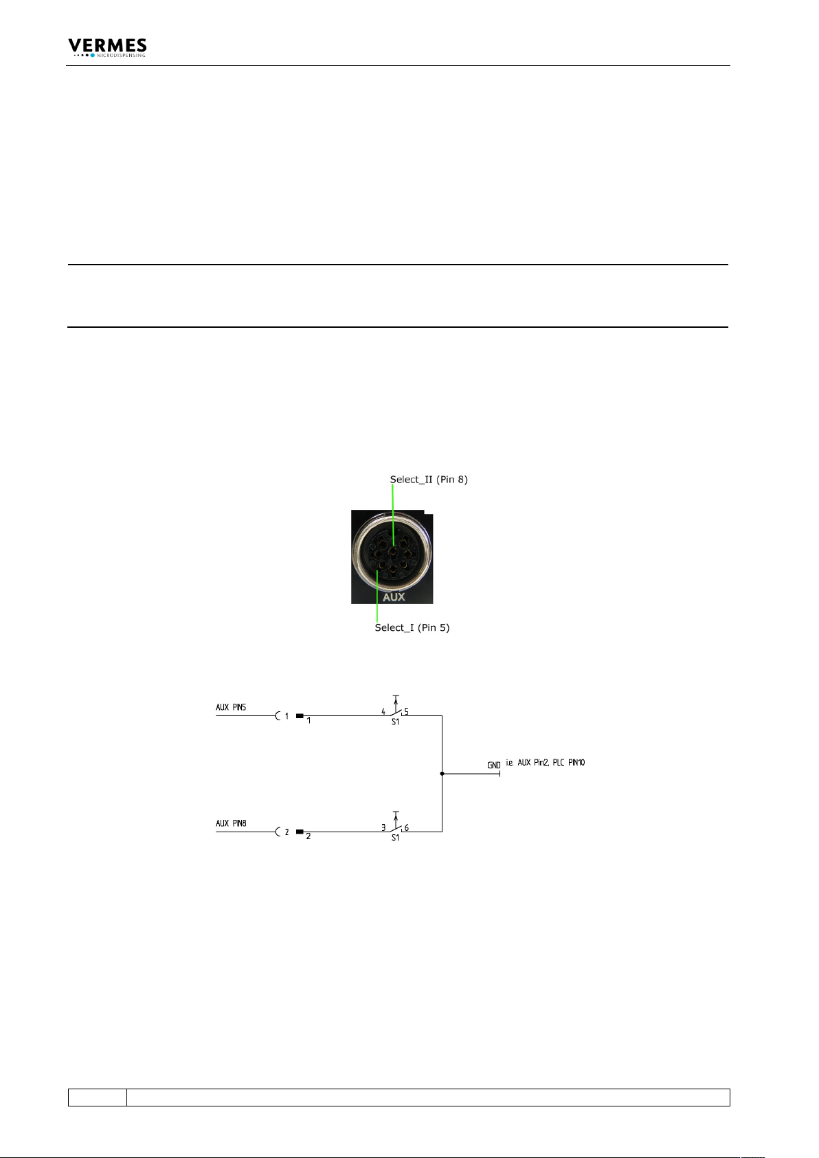
With the pins Select_I (AUX socket Pin 5) and Select_II (AUX socket Pin 8) it is possible to switch
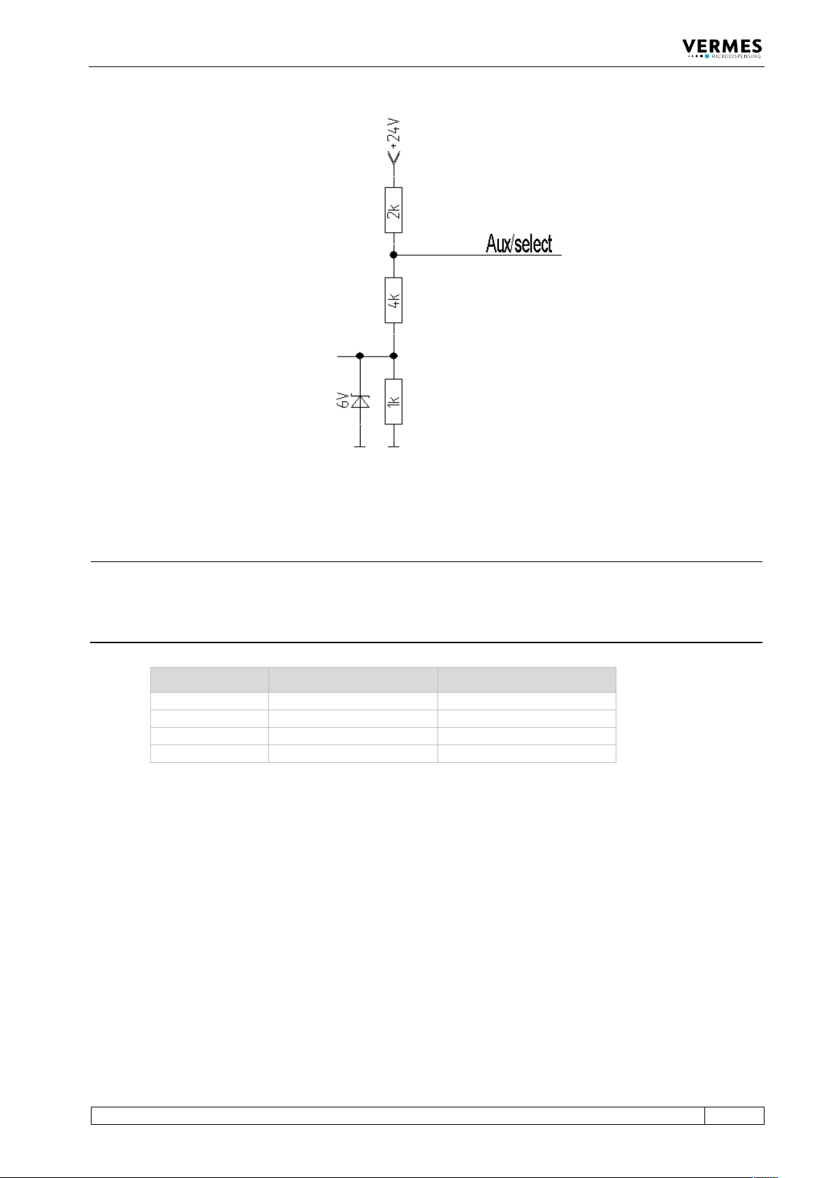
rapidly between different sets of parameters. In their blank state, the select pins are on a high
level (pull-ups to 24 V). You have to switch them to low (Gnd) to select a different setup (see Fig.
26, page 65 and see Tab. 21, page 65). For additional information regarding the AUX socket, see
paragraph 8.3, page 128. You have to switch them before triggering.
Fig. 24: Select Pins
Fig. 25: Schematic of usage of select pins, example
Operation
VTK-TR-BA-171e-1 - User Manual MDS 3080-V
65
Fig. 26: Circuit diagram
INFORMATION
Select pins with other commands
Select pins will be checked for triggering via PLC interface, for the serial commands VALVE:OPEN,
VALVE:AOPEN, SVALVE:OPEN and SVALVE:AOPEN (in the versions without parameters) and when
pressing the [trig]-key.
Setup Select_II (Pin 8) Select_I (Pin 5)
Setup 0
High
High
Setup 1
Low
High
Setup 2
High
Low
Setup 3
Low
Low
Tab. 21: Select Pin settings for the setups
Operation
66
VTK-TR-BA-171e-1 - User Manual MDS 3080-V
7.9 Scenarios
The MDC does not only allow you to save setups of parameters, but also to define combinations
of setups, so called scenarios.
7.9.1 Basics about Scenarios
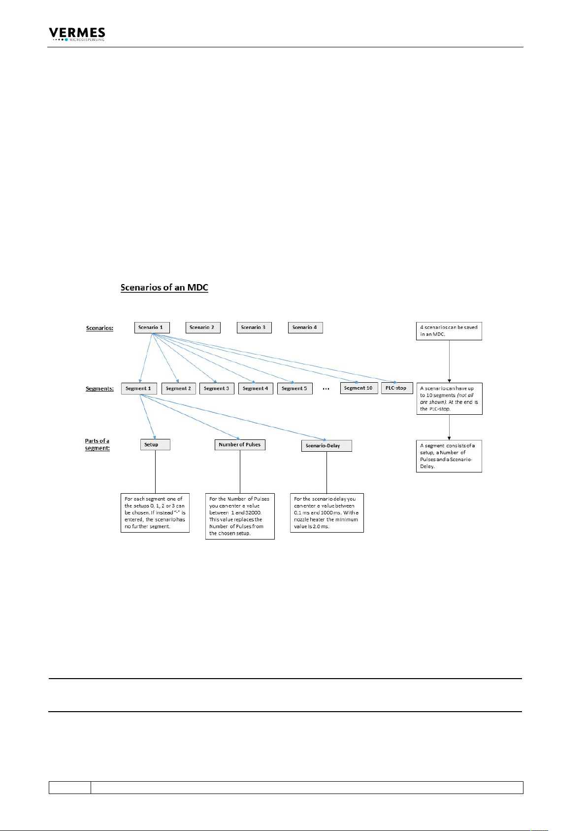
Each scenario consists of up to ten segments, each with a setup, a specific scenario delay and a
Number of Pulses (see Fig. 27). You can define up to four scenarios. You can only choose
between the setups 0, 1, 2 and 3. A maximum of ten segments can be chained together,
consisting of any possible combination of the four potential setups 0, 1, 2 and 3. As soon as you
enter “-” when selecting a segment, the chain ends. No further segments will be shown in the
menu. This is possible even for the first segment you select. In that case, the working
configuration (setup 0) would be executed instead of the scenario.
Fig. 27: Scenarios of an MDC
For each segment in a scenario, you can enter a Number of Pulses. For this segment, the number
then replaces the Number of Pulses saved with the original setup. The value can be between 1
and 32,000 or “infinite”. With “infinite”, the trigger signal defines the end.
The scenario delay marks the time span between two segments. It can be set in the range of
0.1 ms and 1000 ms.
INFORMATION
Scenario delay with heater
With a nozzle heater in use, the minimum scenario delay is 2.0 ms, just like the normal delay.
Each scenario has a scenario PLC-stop, which is either “ON” or “OFF”. If it is “ON”, you can end the
scenario prematurely. The moment the trigger switches to “low”, the scenario ends. When it is