a3369b.pdf - 第57页
Initial Operation 48 VTK - TR -BA- 171e - 1 - User Man u al MDS 3080 -V Fig. 16 : Connec ting th e actuat or cable – step 1 – Step 1: Plug t he cable into t h e corresp ondingly labeled connec tor on the rea r sid e of t…
Initial Operation
VTK-TR-BA-171e-1 - User Manual MDS 3080-V
47
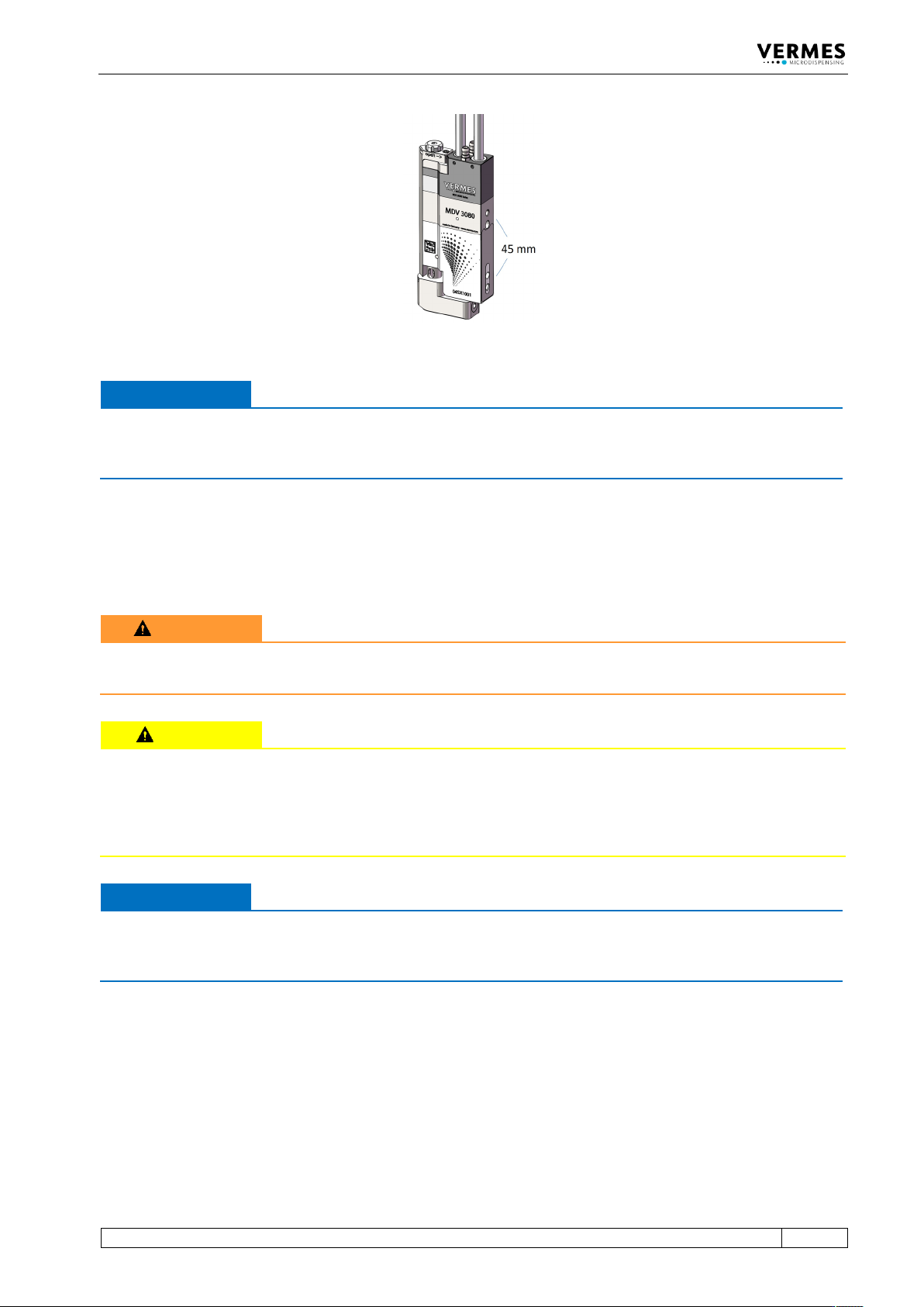
Fig. 15: Distance of the bores 45 mm
IMPORTANT NOTE
Corrosion!
In order to prevent corrosion, all parts used in connection with the valve (screws, fixing plates
etc.) should consist of stainless steel, nonferrous metals or galvanized steel.
6.3.3 Wiring of the MDS
The valve is connected to the control unit by means of a four-pin actuator plug (red) and five-pin
sensor plug (yellow). The plugs are protected by coding against interchanging by mistake.
WARNING
Sw
itch off before removing plug
Never attempt to attach or remove one of these plugs, when the system is connected to mains.
CAUTION
P
lan your cable connections carefully
Make sure to plan your cable run carefully, when considering the wiring, especially if the valve is
included into a more complex system. Your cables cannot hang too loose, since then they might
start to swing and be damaged, because of the vibrations of the valve. On the other hand, you
need enough length in your cables, if the valve is moved in the z-axis.
IMPORTANT NOTE
Switch off for connection or disconnection
Before you disconnect the valve from the control unit or connect it to it, switch OFF the whole
system.
6.3.3.1 Actuator Cable
Power to the piezo element is supplied by the actuator cable, which is wrapped with a red
antikink sleeve. The voltage range is 0 V to 200 V.
Initial Operation
48
VTK-TR-BA-171e-1 - User Manual MDS 3080-V
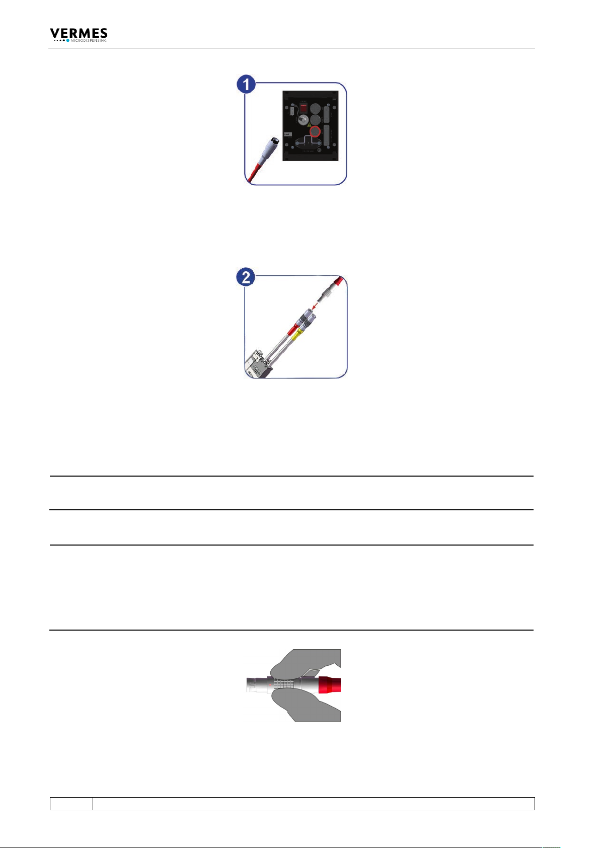
Fig. 16: Connecting the actuator cable – step 1
– Step 1: Plug the cable into the correspondingly labeled connector on the rear side of the
control unit and screw it in place.
Fig. 17: Connecting the actuator cable – step 2
– Step 2: The other end, equipped with a four-pin LEMO connector (corrugated sleeve), has to
be connected to the red marked, looped cable attached to the valve.
INFORMATION
Connecting cables
Verify during the connecting procedure that the red dots on the plugs point towards each other.
INFORMATION
Release latch for disconnection
To secure the connectors there is a latch, which you have to release before disconnection. You
have to grip the corrugated outhousing. Pull back the outhousing of the male connector to
release the latch (see Fig. 18). Then pull both connectors apart without losing the grip and they
will separate.
Do not pull at the cables!
Fig. 18: Connector actuator cable - grip
Initial Operation
VTK-TR-BA-171e-1 - User Manual MDS 3080-V
49
6.3.3.2 Sensor Cable
This cable wrapped in yellow is provided to transfer data from the sensor integrated in the valve
to the control unit. Connect it as described below.
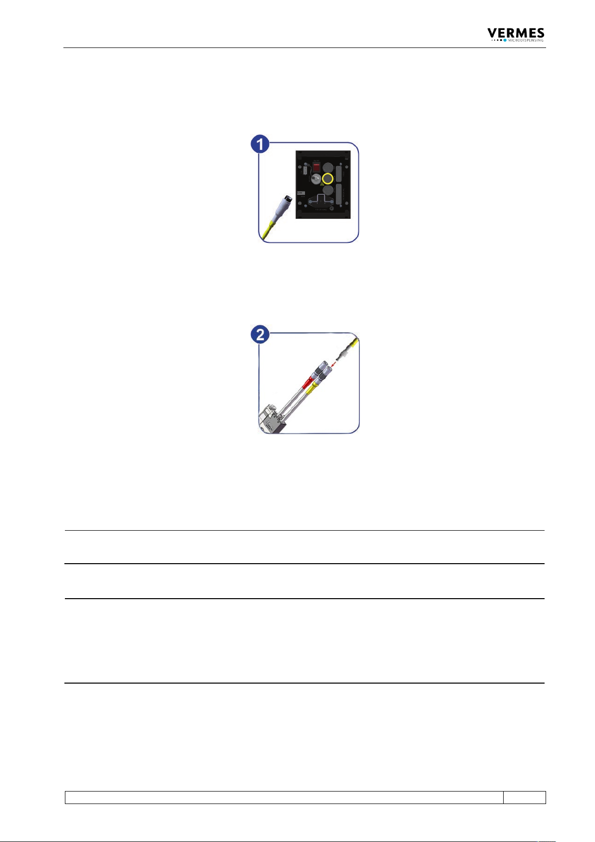
Fig. 19: Connecting the sensor cable – step 1
– Step 1: First, fix the sensor cable to the corresponding socket on the rear side of the control
unit.
Fig. 20: Connecting the sensor cable – step 2
– Step 2: The five-pin connector with a corrugated sleeve has to be connected to the yellow
marked, looped cable attached to the valve.
INFORMATION
Connecting cables
Verify during the connecting procedure that the red dots on the plugs point towards each other.
INFORMATION
Release latch for disconnection
To secure the connectors there is a latch, which you have to release before disconnection. You
have to grip the corrugated outhousing. Pull back the outhousing of the male connector to
release the latch (see Fig. 21, page 50). Then pull both connectors apart without losing the grip
and they will separate.
Do not pull at the cables!