a3369b.pdf - 第39页
Control Unit MDC 30 VTK - TR -BA- 171e - 1 - User Man u al MDS 3080 -V Fig . 6: Submen u “Heater ” (inap pl icable)
Control Unit MDC
VTK-TR-BA-171e-1 - User Manual MDS 3080-V
29
4.5.2 Submenu “Pulse Parameters”
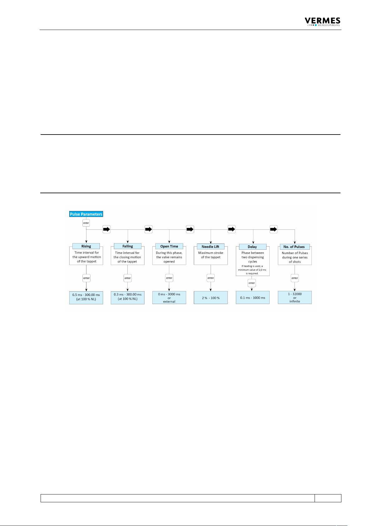
In the submenu “Pulse Parameters”, you can recall and modify dispensing parameters for a
particular process. The limits for these parameters you can find in the diagram. For falling and
rising, the lower limits depend on the needle lift. You cannot enter values outside these ranges.
The dispensing frequency based on the current parameters is shown in the upper right of the
display (as long as “Scenario” is switched “OFF” or always while entering parameters in the
respective submenu).
INFORMATION
Fixed adjust and first drop mode
If either fixed adjust mode or first drop mode (see paragraph 7.12, page 76and paragraph 7.11,
page 71) is “ON”, the parameter “True Needle Lift” is shown instead of “Needle Lift”. It can have a
highest value of 80 % for the fixed adjust mode and of 70 % for the first drop mode. If the needle
lift at the time of switching is higher than this limit, the value will be changed to this limit. You
should not set the TNL to a value larger than the TNLmax. If you do, the red first drop LED
(“function”) is “ON”.
Fig. 5: Submenu „Pulse Parameters“
4.5.3 Submenu “Heater”
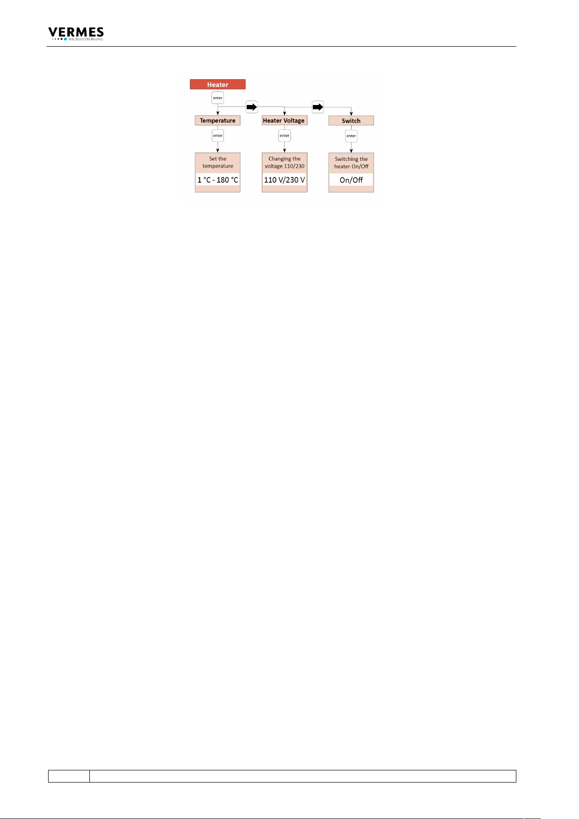
Completely ignore the submenu “Heater”! Since there is no 230 V heater from VERMES, which
would be compatible with the valve MDV 3080-V.
The Microdispensing System MDS 3080-V can only be equipped with a 48 V heater (e.g. the
heater MDH-48-BY, order no. 1014231). This heater cannot be controlled via the control unit MDC
3090-V. You will need an external heater controller (e.g. MFC 3000, order no. 1014981, or MHC
48-1, order no. 1014107). You can find more information in paragraph 7.14, page 77.
Control Unit MDC
30
VTK-TR-BA-171e-1 - User Manual MDS 3080-V
Fig. 6: Submenu “Heater” (inapplicable)
Control Unit MDC
VTK-TR-BA-171e-1 - User Manual MDS 3080-V
31
4.5.4 Submenu “Status”
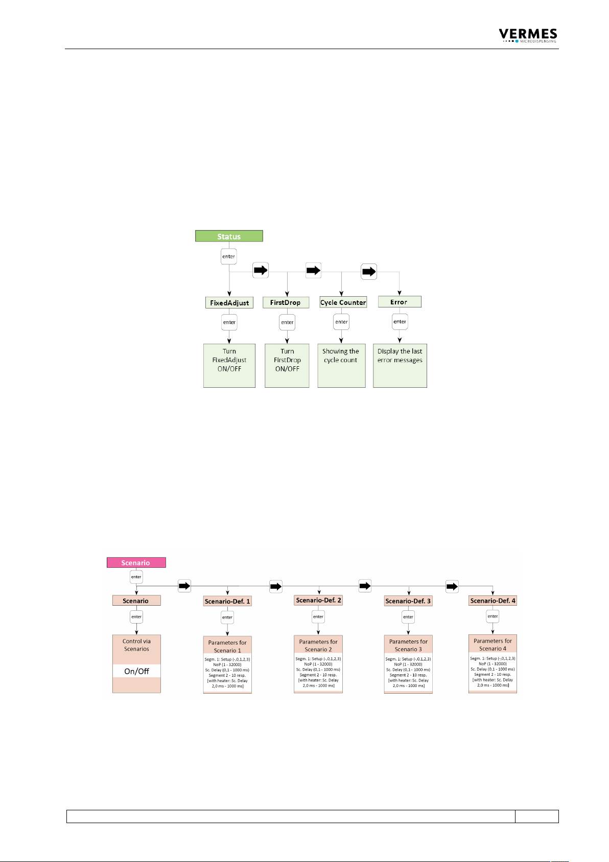
You can use this submenu to switch “FixedAdjust” and “FirstDrop” ON or OFF (see
paragraph 7.12, page 76 and paragraph 7.11, page 71). If you switch “ON” either of these modes,
the red first drop LED shines until you have performed a successful first drop adjust. If you switch
“ON” “FixedAdjust”, you also need to perform a normal adjust.
With “Cycle Counter”, you can check the cycle count of the dispensing cycles.
“Error” shows the latest error messages of the system (up to 50), depending on the system even
with date and time (UTC). Help to solve error messages you will find in paragraph 11.2, page 151.
Fig. 7: Submenu „Status“
4.5.5 Submenu “Scenario”
In the submenu “Scenario” you decide if you want to work with scenarios (see paragraph 7.9.1
"Basics about Scenarios", page 66). You can also enter parameters for pre-defined scenarios. Each
of the four potential scenarios has its own submenu, where you can set those parameters. The
second diagram explains the structure of these submenus. Check there to find the possible limits
for those parameters.
With [→] and [←] you can switch between the four scenarios.
Fig. 8: Submenu “Scenario”
To enter the parameters for a scenario, press [enter] on the respective submenu “Scenario-Def.”
The structure of these submenus is explained in the picture below (see Fig. 9, page 32).