a3369b.pdf - 第33页
Control Unit MDC 24 VTK - TR -BA- 171e - 1 - User Man u al MDS 3080 -V Sensor socket : For t he conn ection of t he sensor cable. Socket for heating : The heat er cable has t o be connected here . P LC - interfac e (15 -…
Control Unit MDC
VTK-TR-BA-171e-1 - User Manual MDS 3080-V
23
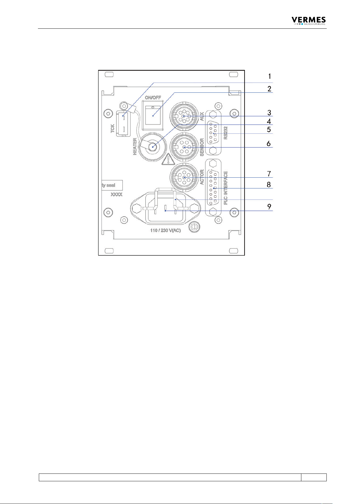
4.3 Back Side
Fig. 2: Back side
1 Thermocouple „Type K“ socket
2 Mains switch
3 AUX socket
4 Socket for heating
5 RS-232C interface (9-pin)
6 Sensor socket
7 Actuator socket
8 PLC-interface (15-pin)
9 Mains connector
Thermocouple socket (TCK):
This element is intended for connection of thermocouples “Type K“.
Mains switch:
By means of this illuminated switch, the unit is switched ON and OFF.
AUX socket:
This connector can be used for supply of an external device (e.g. an optocoupler) or to control
certain parameter setups or scenarios (see paragraph 7.9.3 "Scenario Selection with Select Pins",
page 67). It is one of the three interfaces of the control unit (see paragraph 8.3, page 128 for the
pin assignments).
Actuator socket:
For the connection of the actuator cable.

Control Unit MDC
24
VTK-TR-BA-171e-1 - User Manual MDS 3080-V
Sensor socket:
For the connection of the sensor cable.
Socket for heating:
The heater cable has to be connected here.
PLC-interface (15-pin):
Different inputs and outputs may be connected. For the communication protocol, refer to
paragraph 8.1.1, page 83.
RS-232C interface (9-pin):
Since the system offers the possibility of external programming of dispensing parameters via PC,
a local RS-232C is integrated to receive the data. For the communication protocol, refer to
paragraph 8.2.1, page 119.
Mains connector:
Connects the control unit to power supply.
Control Unit MDC
VTK-TR-BA-171e-1 - User Manual MDS 3080-V
25
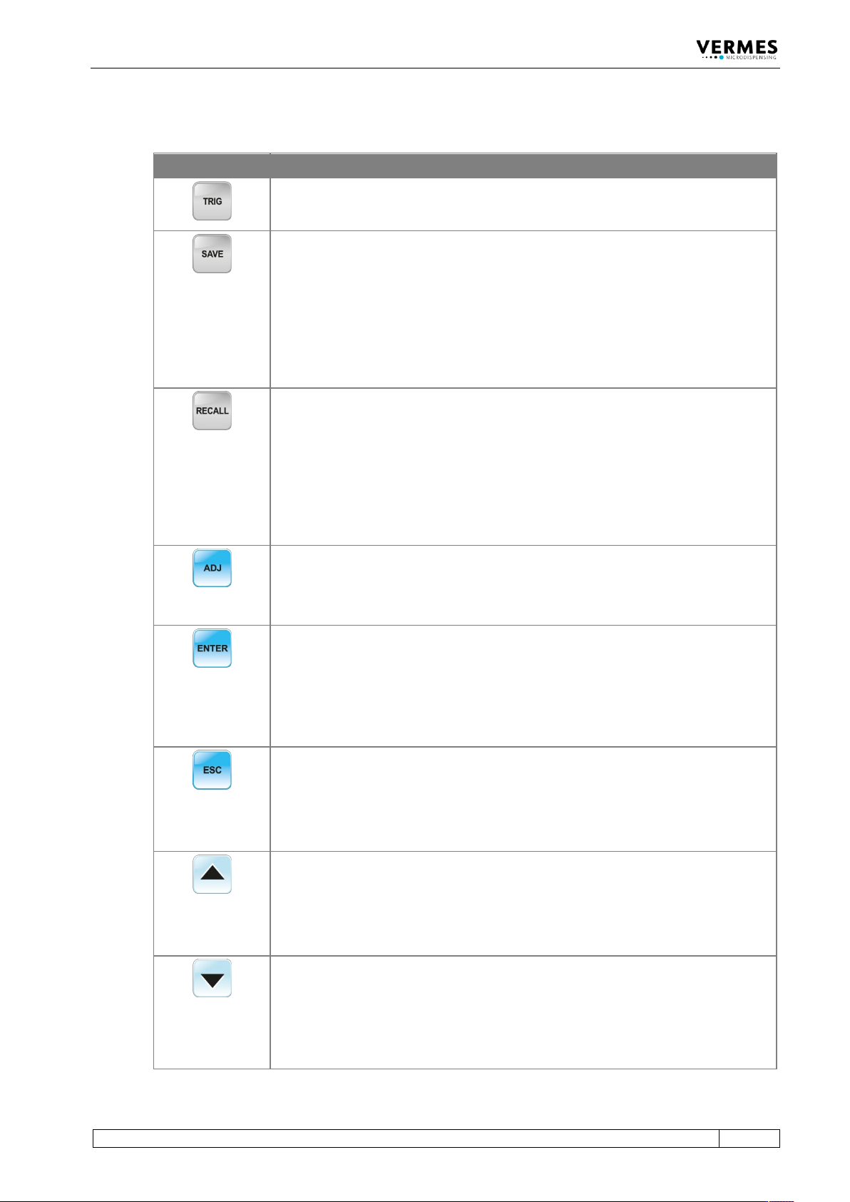
4.4 Function Keys
Function Key Function
Manual trigger key
Pressing the [trig]-key instantaneously launches a dispensing procedure according
to the selected parameter settings.
The [save]-key opens the menu for storing current parameters.
Ten storage locations are available for distinct configuration sets. Each set contains
values for all pulse parameters.
Select the desired storage location by means of arrow keys.
Press [enter] to confirm.
Press [esc] to cancel without saving the selection.
Parameter sets saved in the internal memory can be retrieved any time with the
[recall]-key.
Here you can load the settings stored with [save].
Use the arrow keys to select one of the ten internal storage locations.
Press [enter] to confirm the selection.
Press [esc] to abort.
The [adj]-key is used to start the adjust (see paragraph 6.5, page 52).
It is required during each initial operation and after an exchange of the nozzle unit.
With this procedure, the position of the nozzle insert with respect to the tappet is
preselected.
Pressing the
[enter]
-key confirms the menu selection and opens the corresponding
submenu.
or
The entry of a value is confirmed. The screen changes to the next-higher menu
level.
Pressing the [esc]-key aborts the current action. Values just entered are deleted.
The next-higher menu level opens.
or
Direct access to the next-higher menu level.
[↑]-key
Access to the next-higher menu level.
or
Increasing of a numerical value.
[↓]-key
Access to the next-lower menu level.
or
Reduction of a numerical value.